
Schematic editor
Pages, devices and their structure, live cross references, editing tools, navigators and project storage. The user interface lists the commands and keys.
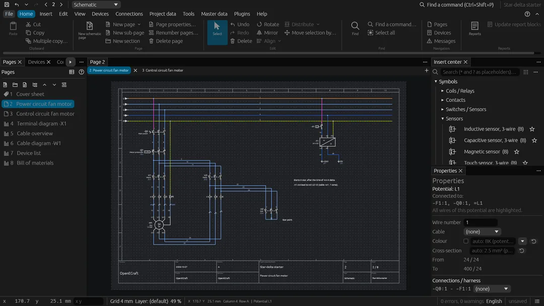
Projects with pages
Multi-line schematic pages (A3, 10 columns / 6 rows, title block), cover sheet and generated report pages. Page navigator with reordering.
Device-oriented engineering
Device tags (-K1, -S3, …) are assigned automatically.
Main function (coil) + auxiliary functions (contacts) form one device. Select a coil and
place contacts: they are assigned to it and numbered (13/14, 21/22, …).
Device boxes and device connection points
Power supplies, measuring instruments and control modules without a library symbol:
Insert › Device box draws a dashed box of any size as a new device (-A1, with its
function text and parts like any other device), Insert › Device connection point
places its connections one click after the other. A point placed on the outline of a
box belongs to the box's device, leads away from the edge it is on and is numbered on
(1, 2, 3 …; 13 is followed by 14); its designation (L, N, PE, +24V, …) is
edited in its properties. Each point is a connection of its own, distinct from
terminals: two points of a box are never connected by the box, they appear as
-A1:L, -A1:N in the connection and device connection reports, and the check reports
a designation used twice on one device. The properties of a point name its device box
(another box assigns it to that device); a point away from its box shows its device
tag, on its box the box shows it. Its designation can be dragged to any place and
aligned left, centred or right. The properties of a box set its width and height:
points on an edge that moves go with it, their wires follow. Moving, turning, copying,
cutting, deleting and saving as a macro take a box with its points; copies become a
new device with their own points. Commands: add_device_box, update_device_box,
add_device_connections (several at a distance, designations given or numbered on),
update_device_connection, list_device_boxes.
A box can also continue a device placed elsewhere: give it the device's tag and choose
its Role in the properties (role of add_device_box and update_device_box). An
Extension adds connection points to the device, for a device too large for one box or
a library symbol that lacks some connections. Its points are new connections, and a
designation the device already has is reported as used twice. A Pin view shows some
connection points the device already has, for example only the supply of a PLC card on
the power page; tick them in the properties (show_device_pins) or place points with
their designations. A point on a view is the connection point it shows: wires drawn
there belong to that point's potential on every page, reports list the connection once,
from the device's own point, and the check reports a view of a point the device does
not have. Neither role is a second main function. The box shows a cross reference to
the device, and the device's main function to its boxes; copied without the device,
these boxes stay on it. A box with a role but no device placed is reported.
Structure identifiers (IEC 81346)
Pages carry a function (=A1) and a location
(+CAB1). Devices placed on a page get its structure (=A1+CAB1-K1); on the page, tags
and cross references show only what differs from the page structure (EPLAN style),
tags are numbered per structure, copy / paste moves devices into the target structure,
changing a page structure can move its devices along. The device navigator groups by
structure; the title block shows the full page name (=A1+CAB1/3).
Structure boxes (Insert › Structure box) give an area of a page its own function,
location (or installation site, product): draw a rectangle and set the aspects it
overrides in the properties; empty aspects are inherited from the page or an enclosing
box, nested boxes resolve to the innermost. A device belongs to the box its main
function's insertion point lies in: it gets the box's structure (=SYS+FIELD-S1 on a
page =SYS+CAB1), its tag on the page omits what the box shows, and its full tag is
what the navigator, numbering, cross references and reports use. An aspect of a tag
equal to the structure around the symbol is inherited, any other is the device's own:
moving the main function into or out of a box, or moving, resizing, changing or
deleting the box, renames the device (all its functions) in its inherited aspects in
the same undo step and keeps its own; a tag that exists already is refused and reported
instead of merging two devices. The symbol properties show where each aspect comes
from. Boxes are copied, pasted and saved in macros with their devices; the check
Structure identifiers reports boxes that overlap without one lying inside the other, and
devices inside a box whose tag has another value for an aspect the box sets.
Commands add_structure_box, update_structure_box, list_structure_boxes.
Live cross references
Contacts show where their coil is (/3.4), coils show a
contact image with all contacts and their locations, interruption points reference their
counterparts on other pages. Connections › Cross references… sets the format (prefix,
separator, row: /3.4, 3-4, /3.4.B), when the structure of the target page is
shown (when it differs, always, never), what interruption points refer to (all
other points, star from the first point, or pairs in schematic order; the check
reports a point without partner) and whether coils draw a contact image. Command:
set_cross_references.
The name and the cross reference of an interruption point follow the arrow: for
horizontal points the name above and the cross reference below the conductor, ending at
the connection point, so that they stay inside the page at its edge; for vertical points
beside the arrow (cross reference below the name). Display in the properties puts
them above, below, left or right of the arrow instead, for all selected points at once
(right of a right arrow: in one line after its tip, for conductors 4 mm apart); with one point
selected, each text can be dragged on its own without moving the symbol, and the
reset button returns to the automatic placement. The places are saved with the project
and used by the PDF, SVG and DXF exports; the cross reference stays a link to its page.
Command: place_interruption_texts.
Connectivity / potentials
Wires, T-junctions (with connection dots), terminals, potential connection points (L1, N, PE, +24V, …) and interruption points are evaluated into nets across pages. Selecting a wire highlights its whole potential.
Editing
Select / window select / move with wires that follow and stay square, rotate, mirror, copy / cut / paste (via clipboard, devices get new tags), undo / redo, texts, grid snapping, pan and zoom. A wire attached to something that moves keeps its direction: a corner or a junction at its far end slides along the wire there (a junction on a rail stays on the rail), otherwise the wire gets a jog or a route around what is in the way, and a wire that cannot be squared without touching another connection stays diagonal. Connection definition points and cable definition lines stay on their wires unless they are moved themselves; a line that cannot stay across exactly its wires stays where it is. With Route the connections of moved items anew (Connections › Wire crossings…, off by default) such a wire is routed again together with the corners after it, up to the next connection point, junction or branch, on the way of the least weight: its length in grid steps, 1.2 per bend and 1.5 per wire crossed; a connection without such a way is squared as before.
A moved wire stays connected too: its end at a connection point of a symbol that
stays gets a new leg from that point (a jog instead where the leg would touch another
connection point or wire), its end on a wire running through slides along that wire,
and other wires at the point stay there; a straight wire keeps its direction and lands
where it was dragged to, a wire held at both ends does not move along itself. Drops
from a moved rail follow it only across the rail, so they keep their place when the
rail is moved along itself. Edit › Keep connections (on by default) turns this off together with
the stretching of attached wires, so that the selection moves alone and leaves its
connections; holding Alt when a drag starts reverses the setting for that drag. To
disconnect one end, select the wire and drag the square handle at that end: only that
end moves, it connects to what it is dropped on and the wire stays square. Commands:
move_items (keep_connections), move_wire_end.
Editing aids: grid sizes 1, 2, 4, 8 and 16 mm (View);
connection points and wire ends off that grid (imported drawings, device boxes of any
size) add invisible grid lines through them, so the pointer snaps to them where they
are nearer than the grid, wires can start at such points and things can be connected
to such wires; a symbol being placed or moved snaps from its own connection points
(and a moved wire from its ends), so they land on such lines and auto-connect joins
them; a
coordinate field in the tool bar (x y absolute or @dx dy relative to the last
point, Enter acts like a click of the current tool); Home › Align (edges or
centres), Distribute (evenly, horizontally or vertically), Move selection by…
and Multiple copy… (n copies at a fixed distance, new tags and terminal numbers);
attached wire ends follow. Commands: align_items, distribute_items, copy_items.
Texts
Free texts with rotation (0 … 359°, e.g. reading upwards along a terminal
strip), left / centred / right alignment, a vertical anchor, word wrap at a set
width, bold / italic / underline, a border and an opaque background, and a hyperlink
(Ctrl + click opens it; clickable in the PDF and SVG export). Special texts show
project and page properties anywhere on a page: placeholders such as {page},
{project} or {prop:Name} (the same as in title blocks, Insert › Special text) are
filled in when the page is drawn. A path function text (Insert › Path function
text) is the function text of all functions in its column that have none of their
own; the device list, terminal, plug and PLC diagrams use it. Texts turn with a
rotated selection; DXF / DWG import keeps text rotation and alignment. Command line /
MCP: add_text, update_text.
Schematic graphics
Lines, rectangles, circles, ellipses, arcs, polylines and polygons (width, colour, dashed, filled), dimensions (aligned / horizontal / vertical, scale, unit), PNG / JPEG images (also in the PDF and SVG export). Layers (navigator › Layers): visible, locked, printed, colour; DXF / DWG export per layer.
Wire crossings and T-connections
Wires that cross without a connection are drawn as a plain crossing, or the vertical
(or horizontal) wire jumps over the other with an arc, a square bridge or a
gap; close jumps on a wire become one. T-connections show a dot, a large
dot or no dot (a plain T); a connection of four or more wires always keeps its
dot, so that it never looks like a crossing. Connections › Wire crossings… sets
both with a preview; the setting is saved with the project and in settings schemes
and applies to the canvas and the PDF, SVG and DXF export alike. Command line / MCP:
wire_settings (jump: none, arc, bridge, gap; jump_wire: vertical, horizontal;
tee: dot, large_dot, none; reroute).
Routing
Auto-connect draws wires between facing free connection points when
symbols are placed or moved; while a symbol is placed or moved with the mouse, faint
dotted lines show the wires it would draw; the wire tool can route around symbols and other wires
(A); collinear wire pieces can be joined. Also as route / autoconnect commands.
Property placement
Drag the tag block of a selected symbol; place further device properties (description, part / type number, manufacturer, designation, connection points, structure) beside it.
Connection point designations are placed beside the lead of their connection point,
moved along it, to its other side or out beside the wire where the symbol's graphics,
wires, nearby symbols or the symbol's other texts are in the way. Drag one of a
selected symbol to place it by hand, or choose left, right, above or below for each
in Property placement; Reset returns it to automatic placement. The placement
turns and mirrors with the symbol and never moves the connection point. Command:
place_pin_label. The designation of a symbol with a single connection point (such as a
device connection point) is dragged freely and keeps its alignment.
Placed automatically, the tag block sits left of a vertical symbol and above a horizontal one. Where it would run into a neighbouring symbol there, it goes on the other side, above or below, whichever is first clear of symbols and wires with all its lines, the cross references included. The tag of a function right beside one of the same device in the same row (such as surge arresters drawn pole by pole) is shown once, at the first of them, like the strip tag of a row of terminals. A tag block placed by hand stays where it is.
Find
Find (Home › Find…, Ctrl+F): searches the whole project (page names and
descriptions, device tags, function texts, free texts, wire numbers, terminals and
pins, cables, part numbers, descriptions) with case and whole-word options, jumps
to the hits and replaces text in free texts, function texts and descriptions
(released pages stay). Commands: find, replace_text.
Navigators
Pages (optionally grouped by structure with the descriptions of the
structure management), devices (select on page, place further functions, rename),
connections (filter, show, select, add a connection definition), cables (cores in
use and free, cable definitions, draw a cable definition), layers and the check.
The Unplaced tab lists what the project data has but the schematic does not: the
channels of PLC cards with a device description that have no input / output symbol
(with their address), and the functions of the assigned parts that no symbol uses
(coils, contacts with their designations), and the potentials defined in the project
that no potential connection point carries yet; drag one into the page (or click it, then
into the page) to place it with tag, address and designations. Command:
list_unplaced.
Languages
English, German, French, Spanish, Portuguese (Brazil), Italian, Dutch, Polish, Czech, Russian, Ukrainian, Turkish, Swedish, Danish, Finnish, Hungarian, Romanian, Chinese (Simplified), Japanese and Korean (View › Language; the editor and the parts manager remember the choice and start in the system / browser language if supported). Chinese, Japanese and Korean come with bundled fonts (subsets of Noto Sans SC / JP / KR); project texts in these scripts also use the system's CJK fonts on the desktop, on screen and in PDF exports (embedded as a subset).
Project texts in several languages
Function texts, page descriptions, free
texts and descriptions are written in a source language; the project's translation
dictionary (Project data › Project languages…) translates them line by line into any
number of target languages, with CSV export / import for translators and a check
for untranslated texts. Project data › Export as PDF in language (command line: export
with language) puts out the documentation per language – project texts from the
dictionary, reports and title blocks in that language (English, German, French,
Spanish; other languages get English report headings).
Project templates
Project templates (in the spirit of EPLAN's basic projects): File › New › New project
from template starts from a built-in template (empty IEC 60204-1 project; machine
with cover sheet, table of contents, structured schematic pages and report pages;
distribution board with single-line overview, climate and short-circuit reports) or
from any project file; Save as project template… writes the current project
without revisions, baselines, review, wiring marks and accepted check messages.
Command line: new_project --template Machine (or a file); new_project --example <name> starts from an example project.
Storage
JSON project files (.oec); the current project and the parts
database are also auto-saved (compressed) in the app's data folder on the desktop and
in IndexedDB in the browser, whose local storage holds only about 5 MB (until the
first write to IndexedDB succeeds they are kept in local storage as well).