
Panel layout, rooms and 3D routing
Imported cards on horizontal DIN rails
OpenECraft aligns the device's clip to the rail centerline. For Beckhoff's 12 × 100 × 68 mm EL I/O housings with 8 or 16 terminals, and the matching EK1100 coupler, the rail center is 63.8 mm from the top. For example, a rail centered at Y = 100 mm puts the top at Y = 36.2 mm. The 35.4 mm dimension is the housing opening for the nominal 35 mm rail. The importer retains a nonzero article center offset and clip-on height. It applies the drawing-based center offset only to matching housings when the catalog center offset is zero. 8-pin terminal · 16-pin terminal · EK1100 housing
A card placed or moved within 4 mm of a free neighboring edge snaps flush to it on the same mounting plate. The placement preview shows the result. Cabinet artwork uses the assigned front view first, then an imported mounting representation. If those are absent, a vendor overview supplies an illustration fitted inside the physical footprint.
Enclosures with their devices at real size in 2D and 3D (in the spirit of EPLAN Pro
Panel), virtual wiring through the ducts, drilling and NC data, enclosure climate,
line-ups, rooms of the building with their floor-standing equipment and pipe runs,
19-inch racks and 3D routing of cables, tubes and pipes. The example projects conveyor,
cabinet_lineup, electrical_room and pump_room show them.
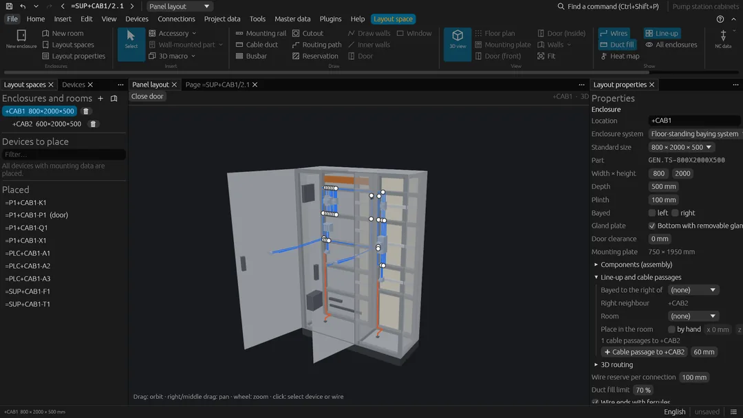
Enclosures and devices
- Enclosures (from a part such as
GEN.ENC-600X800or custom size) with mounting plate. - Mounting rails and cable ducts drawn by length; select one and drag either end to resize it, or move it (devices travel with their rail). Devices are placed from a "devices to place" list with their real dimensions from the parts data (contactor + auxiliary block add up in depth, terminal strips are as long as their terminals and spares) and snapped onto rails; rotate, delete.
- Cut, copy and paste in the front view: right click an item for Cut, Copy,
Paste, Properties and Remove (devices go back to the devices to place), or
Ctrl+X/Ctrl+C/Ctrl+V. Rails, ducts, busbars, cutouts and accessories are copied with the items mounted on them, devices are left out (a device is placed once); cut items leave the layout, cut devices go back to the devices to place. The pasted items follow the pointer until a click places them, on any face of any enclosure;Escor a right click cancels. The commandcopy_panel_itemsdoes the same from the command line and for AI agents. - 2D front view and a 3D view: drag to orbit, right / middle or Shift+drag to pan, the
wheel zooms at the pointer and walks on into a room, a double-click turns to what was
clicked and closes in,
WASD/ arrow keys andQEmove through the view (Shift: faster), the bar in the view has the standard views and Fit (Home); click to select. Walls, ceilings and doors seen from the outside are see-through (Wall opacity in the settings, under Appearance); Hide walls in front leaves out the walls between the eye and the inside, Hide ceiling the ceilings of the rooms. Wires are drawn in their colour (two-colour wires such as green-yellow with a stripe) and, like cables and tubes, as thick as their outer diameter. A cable ends a little before the device it is connected to and its cores part from there in smooth curves, each into its connection point from the side its wires leave it. At its connection point a wire or core ends in its termination: a ferrule (metal sleeve and collar in the DIN 46228-4 colour) or a twin ferrule, a ring terminal (its ring round the connection point), a fork, pin, flat plug or flat receptacle terminal (with its red, blue or yellow insulated sleeve; uninsulated tubular cable lugs from 10 mm²), or the bare copper conductor as long as it is stripped. Each wire end can be given its own termination in the properties of the wire (Wire ends), all cores of a cable at one of its devices in the properties of the cable (Cable ends), and on the command line all ends at a connection point or a device (set_termination); ends without one get a ferrule where Wire ends with ferrules is set, the bare conductor otherwise. A twin ferrule is shared by the two wires ending at one connection point: it is offered only there, chosen for both at once, sized for the larger cross-section and drawn once, at the first of them; with Twin ferrules where two wires share a connection point (orset_ferrules) every such pair without a termination of its own gets one. The check Twin ferrules warns about a twin ferrule with one wire, at a point with more than two wires or for two cross-sections. A ferrule or crimped terminal does not bend: the wire or core runs straight out of its connection point as far as it reaches (with its collar or insulated sleeve) and bends only behind it. The 3D routing plans that straight way out where the space in front of the connection point is free; where it is not (a neighbouring wire, a cable duct close by), the wire bends tighter right behind the ferrule or terminal. The production wire list, the wiring assistant, the machine exports and the bill of materials take the same terminations; through cable glands, wall penetrations and the cable passages between cabinets cables and wires are drawn in one piece, bent round there, several through one cable entry flange or wall penetration side by side. Cable glands are drawn with the models of their parts: outside the hexagon body, neck and dome on the outer surface of their wall, inside the locknut and the end of the thread on its inner surface, in nickel-plated brass or polyamide; routes keep clear of the locknut. In a cabinet without cable ducts on its mounting plate the wires are laid by the 3D routing (see below), from connection point to connection point. - Copper busbar systems (bars drawn, metres and holders in the BOM) and rectangular
or round cutouts in the mounting plate. A device placed over a busbar system is
mounted onto its bars; devices on the same busbar system are connected by the bars,
not by wires. The busbar systems of bayed enclosures that meet at their common side
(the same part at the same height, their ends no more than 100 mm apart) are one
system, joined through the side. The bars lie at the part's
Centre distance(evenly spaced without one) along the system, however short a section of it is; the 3D view draws every bar on its own, on insulating holders reaching just across them, at the drilling positions of the plate but beside the devices that sit in the bars (the transformers the bars pass through), never through them (busbars::holder_places). A busbar terminal strip placed across the bars (busbars::place_on_bars) puts each terminal upright on its own bar, one strip per supply cable; in the 3D routing each of those terminals is a solid of its own (a wire to one goes round the others), and terminals closer than 30 mm along the bars are entered from the front. Each bar is one conductor: the checkbusbarsreports a system whose devices join more conductors than it has bars (part dataBars) as a short circuit, such as a PEN terminal on the bars of the phases or the feeders behind a coupling switch on the busbar before it. It takes the feed side of switches and fuses (the outgoing side where that is the one the other devices share: an incoming strip), each terminal as one conductor, and follows the conductors through the primaries of current transformers. - Mounting layout pages (scaled 2D model view with dimensions) for printing / SVG; cable ducts, mounting rails and busbar systems carry a label with their cross-section and cut length (60 × 100 mm, L = 940 mm) on the longest stretch no device covers, shrunk to fit, only the length (L = 430 mm) where the whole label does not fit. A full one gets it beside its end (else its start), in line with it, up to the next item or the plate edge; it is left out where even there it would be unreadable. Rails, ducts and busbars appear in the BOM by total length (or stock pieces), with the pieces to cut per enclosure and length below each part (no part number of their own, so ERP exports count the material once); enclosures per piece. The panel legend lists every rail, duct and busbar system after the devices with its part number, cross-section (width × height) and cut length.
- Jump between a device in the schematic and its place in the panel layout.
Collision and boundary checks
Overlaps, outside the plate, too deep for the enclosure including a door clearance,
mounted over a cutout, inside the clearance a device needs above and below from its part
data (Clearance: 25 mm); where a device has a 3D model, the models are checked for
penetration, not just their boxes.
Enclosure door
Command and signal devices (pushbuttons, lamps …) are placed on the door (front view
Door); each gets its door cutouts (Ø22.5 by default or from the part data
Door cutout: Ø30.5 / 92 x 68, otherwise its cutouts), placed where the part has them
and turned with the device, checked against the free edge of the door (frame, hinges)
and the device front (a cutout reaching beyond it is reported) and in 3D against the
equipment of the mounting plate; their wires are routed over the hinge; the mounting
layout page shows the plate and every face with items (door, side walls, rear wall,
roof, bottom) side by side.
The door is hinged on the left or the right (Door hinge in the enclosure's
properties, door_hinge of add_enclosure / set_enclosure, part data
Door hinge: right of a maker's enclosure part): the door view shows the hinges and
the handle on their sides, the 3D view opens the door about that edge, and the door
wires run along the door to that edge, over the hinge loop and into the plate's edge
on that side.
Restricted areas
An enclosure part can keep areas of its faces free (Restricted areas in the part's mounting data, imported with the enclosure packages of the Rittal configurator): placing areas take no devices, rails, ducts or busbars, cut-out areas no cutouts or holes, e.g. the hinges, the lock and the stiffening of the door, or the fixing points of the mounting plate. The faces show them hatched (placing areas rising, cut-out areas falling), in the editor and on the mounting layout pages, and the 3D view as translucent areas (placing blue, cut-out orange) that go with their wall or the door. The check reports an item lying in a placing area (Outside) and the cutouts and holes in a cut-out area (Manufacturing); touching an area's edge is allowed. The part editor lists them under Mounting data › Restricted areas (kind, face, place and size), where they are added, changed and removed.
Maker's enclosure models
An enclosure whose part is a maker's part (not one of the built-in catalog) with a 3D model of the enclosure's width and height, as the enclosure packages of the Rittal configurator bring it, shows that model in the 3D view and the 3D exports instead of the generic body, walls, door and plates. The door and what is mounted on it (hinge leaves, locks, seals), as the maker's macro marks them, are translucent and open with the door; a model without that mark opens its front 20 mm. The other triangles go with the wall whose plane they lie in (hidden with it when the walls in front are hidden) or stay inside (mounting plate, gland plate, flanges). Plinths, baying kits and 19-inch rails stay generic. The door opens on its hinge side (the Rittal AX is hinged on the right, see Enclosure door).
Drilling pattern and NC data
Rails, ducts and busbar holders get tapped holes along their length, devices screwed
onto the plate get holes from their part data (Mounting holes: M5: 9,12; 69,72) or two
default holes; NC export per enclosure and face as DXF or DWG (outline, one layer
per hole diameter, cutouts, turned or rounded ones as their outline) or CSV (with the
turn and corner radius of each cutout).
Virtual wiring and duct fill levels
Every schematic connection between placed devices is routed from its connection point (rotated devices, aux blocks, terminal by terminal) into the duct the terminal faces and through the cable duct network (shortest path) → wire list with lengths, wires shown in 2D / 3D.
Duct fill levels: cross sections of the routed wires (with insulation), cables and tubes against the cross section inside the duct (between its walls, base and cover) at its fullest stretch, on the mounting plate as on the walls, ceiling and floor of a room; ducts coloured green / orange / red in the front view, fill level in the duct properties, limit in the enclosure properties (70 % by default); report Duct fill levels, the check warns above the limit and hints above 80 % of it; when a duct is overfull, the wiring is routed again, thickest wires first, and wires take a detour (up to 10 × longer) around stretches they would fill above the limit; cables and tubes routed in 3D do the same around the stretches the wires and the cables before them already fill; the selected device shows its connection points.
Climate
IEC/TR 60890, in the enclosure properties: power loss of the placed devices from the
tech data of their parts (Power loss: 7.5 W) plus an additional loss, effective
surface by installation type (single, in a suite, free-standing, wall mounted, roof
covered), material (heat transfer coefficient), ambient and allowed inside temperatures
→ inside temperature, filter fan air flow (corrected for the altitude of the site),
air/air heat exchanger (W/K, when the degree of protection must be kept) or cooling unit
output, heater output that also keeps the inside above the dew point of the ambient air
(relative humidity); report Enclosure climate, the check warns when cooling is needed.
The heat map of the mounting plate stratifies the mean temperature and adds a plume above every device with power loss data; horizontal ducts hold plumes back (warm air gathers below them), fans and cooling units weaken them.
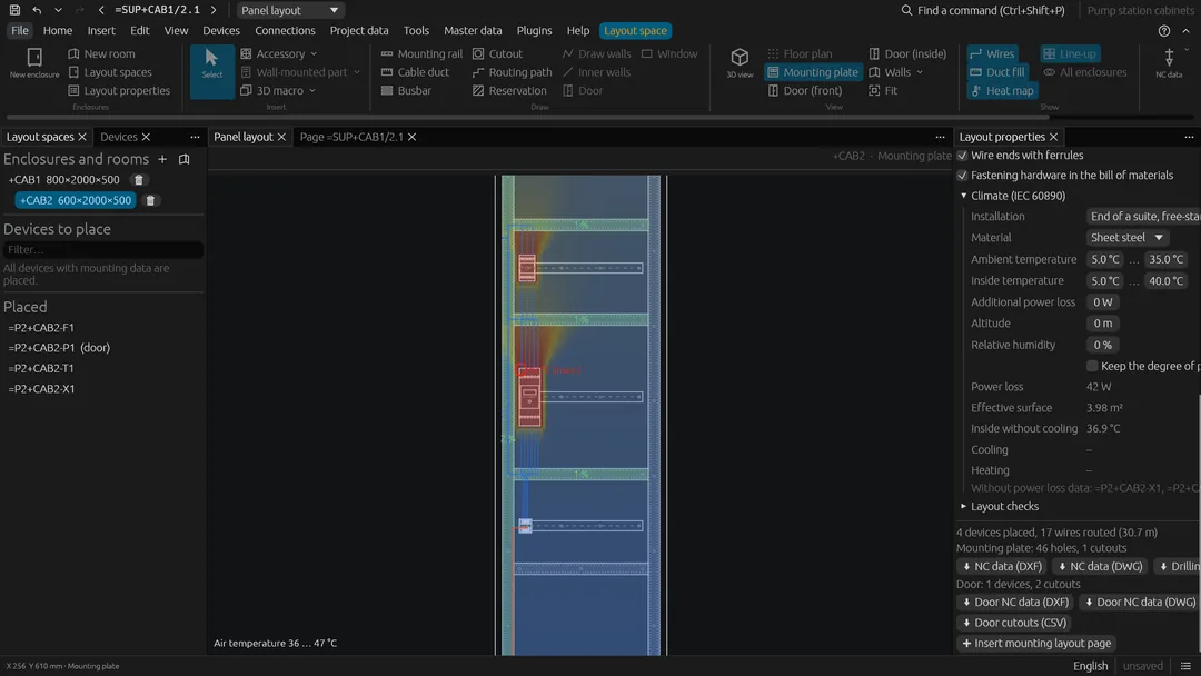
Line-ups
Enclosures bayed side by side with cable passages between them (cutouts in the facing side walls, or sides open to each other); the 3D view shows the whole line-up, wires run from one enclosure into the next. The room view shows all enclosures side by side at their places, each line-up at its position and turn set by hand or taken from the plant layout.
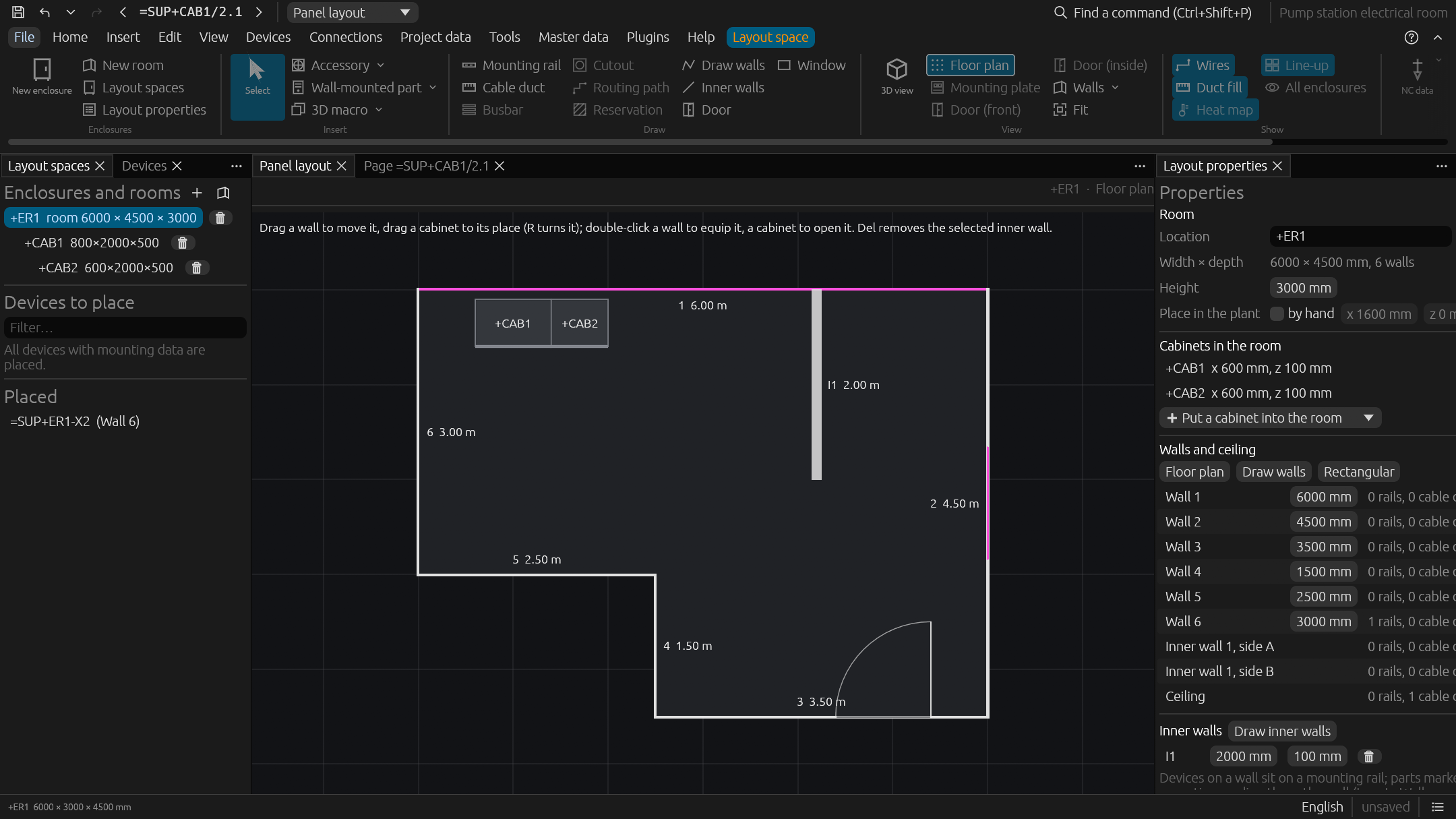
Rooms
Layout space › New room (plugin rooms): a room of the building with its floor plan,
height and place in the plant. The floor plan is a rectangle or an outline of walls at
right angles (L, U or T shaped rooms): Floor plan shows it from above, Draw walls
draws it by clicking the corners (on a 50 mm grid, closed by clicking the first corner
or Enter), walls are dragged to move them or get a length in the room's properties
(commands set_room_outline, set_room_wall).
- Inner walls (Layout space › Draw › Inner walls, commands
add_inner_wall,set_inner_wall) are drawn in the floor plan by clicking their ends (a chain, at right angles; an end near a wall snaps onto it), dragged across to move them, get length and thickness in the room's properties and are removed with Del; both sides (inner1a,inner1b) are faces like the walls. - Doors and windows (Layout space › Draw › Door / Window, commands
add_wall_opening,set_wall_opening) are openings in a wall, placed by clicking the wall in the floor plan or in the view of the wall: a door stands on the floor, a window has its sill height; size, position, sill and how they open are in their properties. Opens (opens) chooses the hinges at the left or right edge (seen from inside the room) swinging into or out of the room, or a sliding leaf moving left or right along the wall. The floor plan draws the leaf with its swing (from the outer surface of the wall when it opens outwards) or the sliding leaf with its way, the view of the wall the opening sign (its tip at the hinges, dashed when the leaf opens away from the viewer) or an arrow. The check keeps the swing of an inward door and the way of a sliding door in front of the wall free of cabinets. - Cabinets (their line-ups) stand in it at a place of the floor plan, dragged there in the floor plan (R turns the selected one about its centre), and move with the room. A cabinet outside the room, across a wall, in an inner wall or in the swing of a door is drawn in the warning colour, and the pointer over it tells why.
- Every wall (seen from inside the room) and the ceiling carry mounting rails, cable
ducts and devices: a device on a wall sits on a rail, unless its part is marked
Wall mounting (part editor › Mounting data, a
WALLbadge in the part trees, filter Only parts for direct wall mounting), then it goes directly on the wall (Insert › Wall-mounted part, also without a device tag). - Outlets, switches and heating (Insert › Outlets, switches, heating): socket
outlets, data and antenna outlets, switches, push buttons, dimmers, room thermostats,
heating circuit manifolds and single-room control boxes (RTL / TH), drawn with their
models in the 3D view. The menu has a tab for outlets, switches and heating, a search,
filters by maker and type, the list and the part picked with its 3D model (drag to
turn it), its size and mounting height (Place on the wall or a double-click places
it). It lists
the generic parts of the catalog (
GEN.SOCKET-F-UP,GEN.SW-2WAY-UP, …, manifoldsGEN.HCM-2…GEN.HCM-12, the number of circuits chosen in the menu,GEN.RTL-BOX) and those of the parts database and of the shipped catalogsgira(System 55),mdt(KNX push buttons, glass push button, room temperature controller) andcosmo(manifolds Standard and Balance, control boxes); a part of a shipped catalog comes into the project when it is chosen. A part with a Mounting height in its technical data goes on the wall at that height (its middle above the floor: socket and data outlets 300 mm, switches 1050 mm, thermostats 1500 mm, control boxes 250 mm) where the wall is clicked. The manifolds have a nozzle for flow and return and one pair per circuit, downwards, for the pipe routing. - The floor (face
floor) carries the parts marked Floor mounting (pumps, tanks, compressors; aFLOORbadge, filter Only floor-standing parts): Insert › Floor-standing part, devices to place on the floor's view, commandmount_on_wallwithfacefloor. They are drawn in the floor plan, dragged there to move them and removed with Del. - Wall penetrations (Layout space › Draw › Wall penetration, command
add_wall_openingwithkindpenetration; 300 x 200 mm, 300 mm below the ceiling unless set otherwise) go into the outer walls and lead into the room behind the wall (up to 1 m away, through rooms turned against each other too): cables, tubes and pipes are routed from room to room through them. The floor plan draws them and the way through the wall dashed;list_roomstells where each one leads. - Building entries (Layout space › Draw › Building entry, command
add_wall_openingwithkindentry; 200 x 200 mm, 600 mm above the floor unless set otherwise) are the house lead-ins of the outer walls: the supply cable, the water main and other lines from outside the building come in through them. A cable or pipe from a device in the room to a device outside the building (its location is none of the rooms and enclosures of the layout, such as the utility's cable distribution cabinet) is routed to the nearest building entry. - Pipe runs (Layout space › Draw › Pipe run, command
add_pipe_run) are drawn on a wall, the ceiling or the floor by clicking their corners (at right angles), 100 mm in front of a wall, 300 mm below the ceiling or 200 mm above the floor unless set otherwise: the hoses, tubes and pipes of the schematic are routed along them like wires along cable ducts. The floor plan shows them dashed. - The outside of the building: every wall of a room also has its outside (faces
outside1,outside2, …, seen from outside, Outside of wall n in the walls menu) and the ceiling its top (facerooftop): façade lights, sensors and cameras go on the outside of an outer wall like on a wall inside (on a rail or, marked Wall mounting, directly), a weather station or other parts marked Floor mounting stand on the roof. Their cables and pipes run through the wall (or the ceiling) right behind them into the room. The check reports such items where another room is right behind the wall or above the ceiling (within 1 m).
The check reports devices on a wall that are neither, rails or devices over a door or window, pipe runs across a door or window, items on the ceiling outside the floor plan, inner walls leaving the room, cabinets and floor-standing parts in the swing of a door or in an inner wall, floor-standing parts on the place of a cabinet or not made to stand on the floor, and cabinets and floor-standing parts outside the room (or across a wall), cabinets higher than its ceiling, wall penetrations that lead into no room. Rooms have no climate calculation and no NC data.
Several rooms stand at their places in the plant (Rear left corner of the room
in its properties, commands add_room / set_room with x, z and angle). The
floor plan of a room shows the rooms around it faintly with their names and cabinets
(those beside it, not the ones on the levels above and below); a double-click opens one
of them. Layout space › Show › All enclosures shows every room and cabinet at its
place in 3D, with the routes between them.
The navigator (Enclosures and rooms) has the site at its root, above the buildings with their levels and rooms and the rooms outside buildings. A click on a room keeps the 3D view when it is shown and otherwise shows the room's floor plan. A click on the site shows the site plan of all buildings in the Layout space (the wheel zooms, dragging moves it, a click on a room opens its floor plan; in the edit mode Site › Move buildings a building is dragged to its place and R turns it by 90° about its middle, with its rooms, cabinets, stairs and roofs and the rooms standing in it without being on one of its levels) or, in the 3D view, all of the plant with its buildings, floor slabs, stairs and roofs; a click on a building shows the site plan with it highlighted. A level clicked while the 3D view is shown shows all rooms of that level side by side at their places, with the cabinets standing in them, the floor slabs and the stairs reaching the level (no roofs); a second click shows all of the plant again. The context menu of the site adds a building, draws the plot boundary or places the reference point, that of a building a level on top or a basement, that of a level a room on it.
Plot boundary and reference point
The plot (Layout space › Site, the context menu of the site, the Plot section of
the Buildings pane; plugin buildings) is the parcel of land the plant stands on.
- Plot boundary (Site › Plot boundary, command
set_plot): drawn in the site plan corner by corner (a click on the first corner, a double-click or Enter closes it, Backspace takes back the last corner, Esc stops); the corners snap to the corners of the rooms (inside and outside their walls), of the shafts and to the reference point. Its corners are dragged in the site plan afterwards. The boundary must not cross itself; the site plan writes its name and area, the pane its corners, area and length. All buildings have to stay inside it: the check Buildings, levels and shafts reports as errors rooms whose outer walls reach outside the boundary, and warns about roofs reaching over it with their overhang and cabinets outside it; the site plan draws them in the colour of errors andplotlists them. - Reference point (Site › Reference point, command
set_reference_point): a georeferenced point of the plant (where it is in the plant, its easting, northing and height above sea level in a coordinate reference system such asEPSG:25832, the direction of grid north in the plant and, if known, its latitude and longitude). Every point of the plant is measured from it: the site plan shows the coordinates under the pointer (easting and northing, or how far east and north of the point), a north arrow, andlist_buildingsthe easting, northing and height of each building's origin;locateconverts between the plant and the coordinate system. IFC exports write the plot's name and the latitude, longitude and height into their site. - Measure (Site › Measure, command
measure): two points clicked in the site plan give their distance, how far east and north the second lies and its direction from grid north.
Buildings, levels and shafts
Layout space › Buildings (plugin buildings) manages the buildings of the plant;
the pane lists them with their levels, shafts, stairs, roofs and the links between
buildings, and draws a site plan of all rooms (one level highlighted), shafts, the
stairs reaching the level shown (steps and walking line), the roofs (eaves, ridges and
hips dashed) with their roof windows, and the links.
- A building (command
add_building) has a place in the plant (x, z and a turn) and levels on top of each other (add_level,set_level: name, height of the floor above the building's ground level, height from floor to floor; a negative elevation is a basement). A new building gets one levelL0at ground level and goes beside what stands in the plant; new levels go on top (L1,L2, …) or below (B1,B2, …). - Rooms stand on levels (room properties › Building, the pane's New room on this
level / Put a room here, commands
place_on_level,add_roomwithbuildingandlevel): the room's place is then measured in the building's floor plan, it stands on the level's floor and moves with the building and its level. A new room on a level is as high as the level less its ceiling slab (300 mm) and goes next to the other rooms of the level. The navigator groups the rooms by building and level: a room dragged onto a level (or onto a room of it) is put on that level; a level clicked in it is selected, and New room then puts the new room on it (a second click unselects it); the context menu of a level and of its rooms has New room on this level, that of a room in a building Take out of the building. Removing a level or a building leaves its rooms where they stand in the plant. - Shafts (
add_shaft,set_shaft) run through a building from one level up to another, at a place of its floor plan: cables, tubes and pipes are routed through them from a room into the rooms above and below whose floor plans the shaft passes, from below the ceiling of one to above the floor of the next. The floor plan of a room shows the shafts through its level. - Stairs (New stair in the pane,
add_stair,set_stair) lead from the floor of one level up to the floor of another: straight, turned once at a quarter landing, turned twice at two quarter landings, with a half landing (two flights side by side) or spiral round a newel, turning left or right. Their foot is the middle of the front edge of the lowest step in the building's floor plan, with the direction of the first flight, the width of the flights and the going of a step; the steps follow from the difference in height (risers near 175 mm). The floor plans of the rooms show the stairs on their level (dashed where they come up from below), the 3D view their steps and landings and the hole in the floor slab above. - Roofs (New roof in the pane,
add_roof,set_roof): flat, shed, gable, hip or pyramid over a rectangle of the building's floor plan (a new one covers the rooms of the building), with the height of its eaves, pitch, overhang and thickness; a gable or shed roof runs along x or z. The underside of the roof starts at the eaves over the walls and rises at the pitch. Where it is lower than the ceiling of a room below it, also on several levels at once (eaves a knee wall above the attic floor, or below the ceiling of the level under it), it becomes that room's ceiling: the room is of different heights at different places. Its walls end under the slope in the 3D view, the view of a wall draws the line where it ends, the floor plan shades the parts under the slope with their lowest height, and the pane andlist_buildingsgive the lowest and highest ceiling of each such room. Roof windows (add_roof_window,set_roof_window; 780 × 1180 mm unless set otherwise) lie in a slope at their middle in the floor plan, with their width along the eaves and their length up the slope; they are seen from outside and from the room below. - PV arrays (PV array under a roof in the pane,
add_pv_array,set_pv_array): rows of solar modules on any roof shape. On a slope they lie parallel to the covering on rails fastened with roof hooks: two rails under each row of modules in portrait, under each column in landscape, the hooks at most the hook distance apart (1200 mm unless set otherwise). On a flat roof they stand tilted towards one side (15° unless set otherwise, facing the direction given) or east-west in pairs on ballasted mounting bases, the rows so far apart that they do not shade each other at a winter sun of 17° (or at a given distance). An array lies on the slope under its middle; its module part (the generic onesGEN.PV-430WandGEN.PV-400W-FB, or modules of the shipped catalogslongiandjinko) gives the size of the modules and its peak power. The mounting material comes from its mounting system: a rail or mounting base of the parts database whose accessories are its roof hooks, rail connectors, end and middle clamps (the one for the module's frame height), ballast and wind deflectors; the generic systemGEN.PV-RAIL-40/GEN.PV-BASE-S15/GEN.PV-BASE-EW10fills in what a system lacks. The modules (unless a device, a PV generator, counts them) and the mounting material go into the bill of materials;list_buildingsgives each array's modules, peak power and material. The site plan draws the modules, the 3D view the modules with their frames and junction boxes, the rails on their roof hooks, the mounting bases and the wind deflectors. Show › Hide PV modules leaves the modules out to show the mounting, Show › See-through PV modules shows them see-through with the wiring under them. The mounting has an earthing point with an earthing clamp (GEN.PV-EARTH-CLAMP, in the bill of materials) on each rail or row of mounting bases; its earthing conductor (earthing: the device of an earthing or equipotential bonding busbar) bonds them and runs to that busbar. The 3D view draws the cabling of each string: the leads of every module: its plus lead (red) and its minus lead (black) out of its junction box, the plus lead of a module meeting the minus lead of the next one at a connector under the modules, and the minus lead of the first module and the plus lead of the last one along the roof, through it beside the array and under it down onto the generator junction box of the array (combiner, a device such asGEN.GAK-2S) and from there a DC main cable (plus and minus) to each inverter (without a generator junction box down onto the inverter), and the earthing conductor (green-yellow) down to its busbar, as far as the devices are placed in the layout. A click on an array in the 3D view opens its properties: where it is, its modules with their electrical data, peak power and area, its mounting with the material and the earthing, its strings with their voltages, currents and the length of their leads, its problems, and the settings of the Buildings pane. A room under the roof shown alone shows the arrays over it and the roof windows from outside too. A click on a roof in the 3D view shows the roof in the Layout properties: its shape, eaves, pitch, roof windows and PV arrays; a roof window or a PV array added there goes where the roof was clicked, and the new array is selected with its properties. - Freestanding PV arrays (Freestanding PV arrays in the pane: PV array in front
of what stands in the plant, Place in the site plan where clicked;
add_pv_arrayandset_pv_arraywithoutbuildingandroof): ground-mounted arrays on the plot, their middle in the plant. They stand in rows of tables facing the direction given (25° unless set otherwise):stackmodules on top of each other on a table (2), the lower edgeclearanceabove the ground (800 mm), two rails under each row of modules on table beams, each beam on a front and a rear rammed post at most the post distance apart along the table (span, 2.5 m), the tables so far apart that they do not shade each other at a winter sun of 17° (or at the row distance given). The generic system is the postGEN.PV-POST-RAMwith the table beamGEN.PV-TABLE-BEAM, the rails, rail connectors, module clamps and the earthing clamp (on the first front post of each table) as its accessories; a mounting system of the parts database (subgroup PV ground post) brings its own. The modules and the mounting go into the bill of materials named after the plot; the site plan and the 3D view of the whole site draw them, a click on one in either opens its properties. Their strings are those of the arrays on the roofs; their leads (and the earthing conductor) run on the back of the modules, down into a cable trench 0.7 m deep and up onto the generator junction box, the inverter or the busbar.plotandlist_buildingslist them with the plot; the checks report freestanding arrays on each other, on a room or cabinet, and outside the plot boundary. - PV strings (String under a PV array in the pane,
add_pv_string,set_pv_string,pv_strings): the modules of an array in series as strings, several strings of a kind in parallel, each on an MPP tracker of an inverter or charge controller (a device whose part has PV input data:Max. PV input voltage,MPPT voltage range,MPP trackers,Max. input current per MPPT,Max. short-circuit current per MPPT; the generic invertersGEN.INV-PV-10KWandGEN.INV-PV-40KW, the Victron Inverter RS Smart Solar and SmartSolar MPPT have them). From the module's data sheet values (Open-circuit voltage,Short-circuit current,Voltage/Current at maximum power, the temperature coefficients of Voc, Isc and Pmax) and the cell temperatures of the design (-10 / 25 / 70 °C unless set otherwise) follow the highest voltage (open circuit at the lowest temperature), the mean and the lowest voltage (at maximum power at the mean and the highest temperature, with the coefficient of the power), the current at maximum power, the short-circuit current at the highest temperature and the power. The report PV strings lists every string with these values, the total power and the temperatures. The check reports strings whose highest voltage exceeds the greatest input voltage of their inverter or the system voltage of their modules, strings below or above the MPP range of their tracker, trackers the inverter does not have, trackers whose strings together exceed their short-circuit or input current or differ in voltage, and arrays with more modules in strings than they have or modules in no string. - Earth electrodes (Earthing and lightning protection in the pane,
add_earth_electrode,set_earth_electrode): a foundation earth electrode in the foundation slab of the lowest level, a closed ring 100 mm inside the outer walls divided by strips across into meshes of at most 20 × 20 m (GEN.ER-STRIP-FE30, its spacers every 2 m and cross connectors), a ring earth electrode in the soil a metre outside the walls and half a metre deep (GEN.ER-STRIP-V4A30), and earth rods at a place of the floor plan, driven from half a metre down (sectionsGEN.ER-ROD-1500, tip and clamp). Each electrode has a material (hot-dip galvanised steel, stainless steel V4A, copper, copper-bonded steel) and a diameter (of a rod, or of a round wire instead of a flat strip); its part is the one of the parts database or the catalog of that material and diameter (by the technical dataMaterialandDiameter) unless one is chosen. The outer walls are the rectangle the roofs cover, otherwise that of the rooms. An electrode connected to a main earthing busbar (a device) runs up to it with a connection lug. All of it goes into the bill of materials. - Lightning protection (
set_lightning_protection,add_air_rod,set_air_rod): of class I to IV, an air-termination system of conductors on the ridges and hips of pitched roofs and round the edge and as a mesh (5, 10, 15 or 20 m by class) on flat and shed roofs, and air-termination rods joined to them; down conductors round the outer walls at most 10, 10, 15 or 20 m apart (at least two, or as many as given), each from under the eaves to its test joint a metre above the ground and on into the soil to the ring earth electrode (otherwise the foundation earth electrode or the earth rods), the roof conductor from the eaves over the roof to the air-termination system. The material and diameter of the conductors and of each rod choose their parts, the mounting hardware is the conductor holders on the roof and on the walls (roof, ridge or flat roof holders, wall holders with or without a spacer) at a distance of their own, a rod stands in a rod holder or on a concrete base; the height of the test joints is set too. The round wire, its holders, the rods with their holders or bases, test joints, earth entries and clamps go into the bill of materials. A click on an electrode, a conductor or a rod in the 3D view or the site plan opens its properties with all of these settings. The PV arrays on the roofs have to lie in its protection by the protection angle of the class (70 - 79° up to 2 m above the surface, down to 23° at the radius of the rolling sphere). The 3D view and the site plan draw the electrodes and the system. Site › Earthing and lightning protection adds them to a building: foundation and ring earth electrodes, earth rods and air-termination rods clicked into the site plan, lightning protection with its class. - Links between buildings (
add_site_link,set_site_link): a cable trench, a conduit or a cable bridge from a building entry of a room to a building entry of a room in another building, through corners in the plant. Routes pass them like a wall penetration; their length is given or follows the way (down to 800 mm below the ground for a trench or conduit, at the height of the higher entry for a bridge).
The check Buildings, levels and shafts reports rooms on levels that are gone, rooms
higher than their level or overlapping on one level, levels overlapping each other,
shafts joining no two rooms, cabinets and floor-standing parts standing in a shaft,
links whose building entries are gone, stairs without valid levels, with a rise outside
140 - 200 mm or breaking the step rule (twice the rise and the going 590 - 650 mm),
roof windows off their slope or across a ridge or hip, rooms the roof comes down to the
floor of, cabinets higher than the sloped ceiling at their place and items on the walls
or the ceiling above the slope, PV arrays off their roof or across a ridge, a hip or its
edge, tilted on a pitched roof, over a roof window or over each other, freestanding PV
arrays on each other, on a room or outside the plot boundary, and PV arrays
whose device is missing or counts another number of modules or whose earthing busbar
is missing, earth electrodes whose busbar is missing, earth rods inside the walls,
lightning protection without earth electrode or with fewer down conductors than its
class needs, air-termination rods off the roofs and PV arrays outside the protection
of the air-termination system. Example 15 (plant_buildings) shows a main building
with two levels and a shaft, a pump house linked by a cable trench through which a
motor cable is routed, façade lights and a weather station on the roof; example 16
(office_building) adds an office building with an attic under a gable roof, a stair
turned at a quarter landing, roof windows, a PV array of ten LONGi modules on rails and
roof hooks in the rear slope with its inverter and the bonding busbar of its mounting
on the attic's gable wall, a foundation earth electrode on the main earthing busbar, a
ring earth electrode and a lightning protection system of class III with an
air-termination rod, outlets and switches of Gira and MDT and a COSMO heating circuit
manifold.
In 3D, Layout space › Show › Whole building shows the building of the room shown with all its levels and rooms, their floor slabs, the stairs and the roofs; All enclosures shows every building of the plant this way. Roofs and gable walls are seen from outside like the walls (translucent, or left out with Hide walls in front); Hide ceiling leaves out the ceilings and the roofs to look into the building. The plant in 3D draws the plot boundary on the ground and the reference point as a post.
Floor plans on paper
Electrical floor plans are drawn on the architect's drawing of the building. A
floor plan on paper goes under a level (Buildings pane, choose the level of the
site plan, Floor plan…; command line import_floor_plan): a picture (PNG, JPEG,
TIFF, GIF, WebP, BMP) or a page of a PDF file, a scan (also those of office scanners,
which split a page into a background picture and black and white fax masks) or a
drawing (its lines and filled areas; texts are not drawn). Of a PDF file with several
pages the page is chosen in the pane. The site plan shows it under the level's rooms;
the picture is kept in the project as a grey PNG (crate openecraft-scan reads the
files, openecraft_core::panel::floorplan holds the rest).
- Scale and place (Scale, Resolution, Top left corner, Turn, Shown;
command
set_floor_plan): the scale of the drawing (1:100 for a new one) and the resolution of the scan (from the PDF page, 150 dpi for a picture) give the size of a pixel in the building. Measure (commandcalibrate_floor_plan) sets the scale from two points clicked in the site plan and their distance, a dimension of the drawing. The top left corner of the picture lies at a point of the building's floor plan, the picture turned about it like a room. - Area (Pick,
areaofset_floor_plan): the part of the picture the rooms are found in, without title block, sections or the other drawings of the sheet; shown dashed. - Find rooms (command
detect_floor_plan) finds the walls, doors, windows and rooms in the floor plan and shows them in the site plan: the rooms outlined, doors in the colour of warnings, windows blue, a door swing as a dot at its hinge. Nothing changes yet. - Make rooms (command
trace_floor_plan) makes a room on the level of each room found (+ROOM1, …): its outline the inside faces of its walls, as high as the level less its slab, at its place in the building; a door goes into the room it opens to (its swing drawn) or the smaller of the two rooms, hinged at the side drawn; a window into the room behind it. Rooms whose outline is no outline of walls at right angles are reported and left out. The floor plan stays under the level to check the rooms against it and to draw on; Remove takes it away, the rooms stay.
How the rooms are found (openecraft_core::wallscan, pure image processing, no
model): walls drawn filled, shaded or hatched (the way cut walls are drawn) at right
angles to the edges of the sheet.
- Ink: a pixel clearly darker (10 levels) than the paper round it (the brightest level within the thickest wall, measured on the sheet shrunk; scans fade and yellow unevenly), after a 3 × 3 median that removes specks.
- Walls: the ink opened morphologically by the thinnest wall (90 mm): text, dimension lines, door swings and the lines of windows go, the filled walls stay. Of what is left only large parts away from the edges of the sheet are walls.
- Straight pieces: runs across a wall (a column of a wall along x) as thin as a wall that keep their place over at least twice their thickness; runs reaching over a piece (a wall meeting it, a blot of pencil on its side) carry it on.
- Openings: from the free end of a piece (not where another piece meets it) a ray along it in the rows of its middle to the next wall: as long as a door or window (0.5 … 5 m) in most rows. Ending at a wall across it (a door beside a corner) it is at most 1.5 m; wider only up to the next piece of the same wall (a window between two pieces). An opening whose two sides are joined anyway (a blot in a room) is none.
- Rooms: the free areas enclosed by the walls with the openings closed (those reaching the edge of the sheet are outside), at least 1 m². Their outline: cut along the lines where the border runs for at least 150 mm, the cells of these cuts mostly inside the room make up the floor plan (walls at right angles, no step shorter than 75 mm).
- Doors and windows: an opening between two rooms is a door; one to the outside a window when lines run through it along the wall (glass, frame, sill), else a door. A quarter circle of ink from one end of a door into a room is its swing.
On the scanned plans of a house from 1972 (1:50, 150 dpi, pencil) it finds the rooms of the ground floor with their doors and windows in half a second; walls drawn as two lines without filling, slanted or curved walls, and sheets scanned askew are not found yet. The rooms found are a start to check and correct: rooms joined by an opening without a drawn door are one room, and stairs or chimneys are walls.
Installation: outlets, switches, lights and their circuits
The installation plan of a level is drawn in the Buildings pane (choose the level of
the site plan) on its floor plan; plugin installation, openecraft_core::installation.
- Placing (Place with a part chosen; command
place_installation): a click in a room of the site plan puts a socket outlet, switch or light there: a ceiling light (GEN.LAMP-CEILING-LED,GEN.LAMP-DOWNLIGHT-LED, parts with Ceiling mounting: yes) on the ceiling where clicked, anything else on the wall nearest to the click (within 0.8 m) at its mounting height (outlets 300 mm, switches 1050 mm, wall lights 2000 mm). The site plan draws them with the symbols of installation plans (IEC 60617-11) in the colour of their circuit; in 3D they are the parts' models. The 3D menu Insert › Outlets, switches, heating has a tab Lights too. - Final circuits (New circuit, commands
add_circuit,set_circuit): a protective device of the distribution board (a circuit breaker, RCBO or fuse of the mains in the schematic or single-line diagram, chosen from a list that marks the spare ones: nothing behind them yet; commandlist_breakers), a cable (type, cross-section; 3 × 1.5 mm² unless three-phase) and its items in the order the cable runs to them: Wire, then click them in the site plan (a click on one of the circuit takes it out). The cable starts at the distribution board the protective device is placed in (or one chosen). - Cable length (Length,
list_circuits, report Installation circuits): from the top of the board to each item in turn in the horizontal installation zone 300 mm under the ceiling (DIN 18015-3), along x and z of the plant (along the walls, not across rooms), up and down in the vertical zones of the items, up or down between levels, 0.3 m for each box: an estimate for planning. Write cable lengths (write_circuit_cables) writes type, cross-section and length (to the half metre up) into the cable list, a new cable-W<n>for a circuit without one. - Voltage drop from the supply (From the supply;
total_drop_percentoflist_circuits): per cable ΔU = k · I · L · (ρ / A · cos φ + X' · sin φ) (k = 2 single-phase, √3 three-phase, ρ of copper at its operating temperature of the electrical settings, X' = 0.08 mΩ/m, cos φ 0.95 unless set). The circuit's cable carries the rated current of its protective device, or the load given; the feeder cables from the supply to the distribution board (those the short-circuit calculation follows, with their lengths in the cable list) the design current of the protective device upstream (load calculation) or its rated current; a planned protective device takes the feeder of another one in the same board. The sum is checked against the limit of the rule sets (Voltage drop); the tooltip tells the feeder's share. - Devices and single-line diagram (Single-line page,
installation_overview): the socket outlets, switches and lights of the circuits get device tags in their room (+ROOM1-XD1socket outlets,-SF1switches,-EA1lights) with their parts, and generated overview pages show each circuit as a single-line diagram: its protective device (single-line circuit breaker, the same device as in the schematic), its cable and its items with their installation plan symbols, rooms beside them. The pages are made again each time. - New protective device (+ beside the protective device,
new_circuit_breaker): a planned miniature circuit breaker of 16 A (10 or 32 A by command), single- or three-phase like the circuit,-F<n>, starting in the board most circuits start at. It is drawn in the single-line page; single-line → schematic makes it a 1-pole (or 3-, 4-pole by its part) breaker of the schematic, to connect to the supply. A single-line circuit breaker stands for 1-, 2-, 3- and 4-pole breakers. - Check Installation circuits: circuits without protective device or board, protective devices not in the schematic or feeding several circuits, cables thinner than their protective device asks (current-carrying capacity under the installation conditions), voltage drops above the limit, items gone; socket outlets and lights in no circuit (information).
House connection boxes
The enclosure system House connection box (house_connection, command
add_enclosure with system house_connection) is the utility's box at the building
entry: glass-fibre reinforced polyester (RAL 7035, IP54) with a hinged, sealable cover
and a mounting plate, in two standard sizes (GEN.HAK-255X415X144 for NH00,
GEN.HAK-410X720X185 for NH2). Its cover opens in the 3D view like the door of any
enclosure. Inside go the NH fuse base (GEN.NH2-BASE-3P-400A, fed from below: the
supply cable comes straight up to its line side through a gland in the bottom, the main
cable leaves straight up through the top) and the PEN terminal block
(GEN.TB-PEN-240-V). The example building_services hangs one on the wall above the
cable entry, with the main earthing busbar (GEN.MET-BAR-10) and the lug of the
foundation earth electrode (GEN.FE-LUG-V4A-10, symbol Earth electrode) beside it.
Distribution cabinets with component modules
A manufacturer's enclosure part that comes with its plinth says so in its data
(Plinth: 200): a new enclosure of it stands on the plinth, which is drawn and
exported but is no part of its own in the bill of materials (the Hager univers
cabinet HAG.FR25S2, 1850 mm + 200 mm plinth, five fields, protection class II).
Its mounting plate is placed by Mounting origin: 25/12.5/20 (the top left corner
of the plate's front from the left, the top and the rear of the enclosure, mm; the
plate keeps the same distance on the right and at the bottom), as the enclosure
packages of the Rittal configurator give it (parts). A plate that is not centred
also gives its size (Mounting size: 500 x 575; mounting_size of add_enclosure /
set_enclosure). A maker's enclosure
part that names its system (Enclosure system: compact) gets that system's walls and
data but stays the part of the enclosure; only enclosures of the built-in catalog
follow their size with the system's body.
Distribution systems build the cabinet from component modules: a module the device
stands on is an accessory mounted under the part (HAG.UE31E1B under the NH1 fuse
switch disconnector HAG.LT153, HAG.UE31SS400 under the current transformers), so
the device takes the module's footprint and depth and the part sits in front of it.
The example pv_transformer_metering builds such a cabinet field by field after a
real one: connection point zone and surge arrester, consumption metering with NH1
isolation on the busbar, transformer module above it, voltage paths and load break
switch (power flows upwards through the field: the conductors run from one device
straight into the next), the NA protection, the generation metering below the coupling
switch and the busbars of the feeders; lifting eyes in the roof, the cables of the
consumers through the bottom, the supply from below; the two meter cabinets of the
distribution system operator with their test terminal blocks beside it. Cable entry
flanges (part subgroup Cable entry, a membrane taking several large cables, such as
the univers FZ402) are ways in for the 3D routing like cable glands. The example
industrial_main_distribution bays two univers cabinets, open to each other, into the
main distribution of an industrial plant: the aluminium supply cables on busbar
terminals and through an entry flange in the bottom, the transformers of the metering
in the supply busbar, a 185 mm busbar system through both cabinets with vertical NH
fuse switch disconnector strips, the current transformers clipped in behind the
measured ones, the coupling switches of the NA protection fed from busbar terminals.
Neither has cable ducts: every conductor in them is laid by the 3D routing, so the
high currents run over the bars and only what can be bent with its radius is a wire.
19-inch racks
The enclosure system 19-inch rack (rack19, Layout space › New enclosure, command
add_rack or add_enclosure with system rack19) is a frame with a perforated door
and two pairs of 19-inch mounting rails (IEC 60297) instead of a mounting plate; its
standard sizes run from a 12 U wall rack to 47 U, and the rails are a part of the bill
of materials (GEN.RK-RAIL-42U). Its rack units (1 U = 44.45 mm) are numbered from the
bottom beside the rails in the front view and on the mounting layout page.
- 19-inch parts are as wide as a 19-inch panel (482.6 mm) and a whole number of
units high (technical data
Rack units: 2): the catalog has a network switch, a patch panel, a PDU, a server, a UPS, blank panels, a shelf and a cable management panel. Insert › 19-inch part mounts one in the highest free units of the rack shown (commandmount_in_rackwithunit, counted from the bottom); placed or dragged, devices and parts snap onto whole units, centred, their front panel on the front rails, and are held by the rails (no holes in a plate). - Units taken twice are collisions; the check reports 19-inch parts outside the units
and, as a hint, other parts on the mounting level (they need a shelf or a mounting
plate). Report 19-inch rack elevation (and
list_racks) lists the parts of every rack from the top with their units and depths, and the free units. - Racks bay into line-ups and stand in rooms like other cabinets.
3D routing
Cables, tubes and (optionally) wires are routed through the line-up: in cable ducts, along routing paths drawn over the mounting plate, or freely around the devices; segregation of the classes power, control, signal and fluid, routing reservations, bend radii, cable bundles with their branches, shield terminations (shield clamp rail, pigtail) and their checks; routes can be frozen for production and stay as they are until they become invalid.
The wires of a cabinet with cable ducts on its mounting plate run through the ducts (layout setting Route wires in 3D routes them like cables instead). In a cabinet without cable ducts, and in a room, there is nothing to lay them in: every wire is routed in 3D from connection point to connection point. It leaves each connection point straight on in the direction the point gives, as far as its bend radius, and comes into the other one against the direction that one gives, never past it and back (through the box of its own device where the point lies inside it, such as the terminals of a switch on its module, never through another device that stands right before the point), keeps half its thickness clear of everything, bends with its radius only, and keeps apart from every other route and from itself (where its ends lie too close for its bend radius it runs round in a loop that never comes back across or alongside its own way, the bends at its corners and the nozzle it comes out of; where there is no such loop it is not routed); routes come together only where they come up to the same device, and there they lie side by side: a route never runs across another one it comes together with (it may only on its own way out of a connection point, or where it comes up to the device the other one ends at, and goes round it there too where that costs little). The straight way out of every connection point and cable entry stays free until its own route is laid, so that no other route runs across a terminal, and only a route out of a connection point right beside it shares it. Of the wires of a cabinet as thick as each other the shortest is routed first: between two devices the inner conductors lie nearest to them, the outer ones go round them. A wire that finds no such way is not drawn: it is reported as an error (… cannot be routed: no way that keeps half its thickness clear of everything and bends with its radius of … mm). The usual causes are a conductor too thick for the room between its ends (a busbar cross-section drawn as a wire: mount the devices on a busbar system instead), connection points that face away from each other, a terminal strip right below a switch, or two ends closer to each other than the bends between them need (a cable entry right below the box it leads into, two fittings one above the other with their ports on their sides). The messages pane jumps to a connection point of the wire or cable, and the 3D view shows a red note with the reason at each of its ends in place of the route.
The routing works on a grid (25 mm in a cabinet, 50 mm in a room); a connection point lies where it lies. The 3D view draws a route straight out of its connection point: its first corner lies on that line, the stretch after it leans over or comes back onto the grid on a slanting piece, short stretches in between are moved along. Where the way straight out of a point is barred and the route starts from the cell beside it, it needs room there for an S-bend of its radius onto that line (or to lean over to it), otherwise it is not routed. Ways that run together lie side by side on lanes; a way changes from lane to lane on a slanting piece of a stretch, never in a step at a corner, and a jog too short for the bends of its two corners is drawn as an S-curve of the bend radius. A cable ends on the bend of the corner before its cores part where it is cut there; the cores part within the box of their ends, and a core to a terminal behind others of its strip (one above the other on the bars) passes them in front of the device. Where two routes still cross each other right at a device they both come up to, the view lifts one over the other more sharply than their bend radius allows.
A cable between two cabinets that stand in no common room is routed in each of them to
one of its cable entries (a note tells that the way between them is not part of the
layout); every cable takes an entry of its own where there are enough that fit it. The
cables through one cable entry flange go through its membrane (part data Cutout)
side by side, each at a place of its own, the cable's thickness and a centimetre
apart: the free place nearest to where the cable heads, the middle where none is free.
Between rooms, a route passes the wall penetrations, shafts and links between buildings that join them, through as few of them as possible: through the first room to a penetration, through the rooms between, through the last room to its end (its legs per room and cabinet in the routing list); its length includes the ways through the walls, shafts and links. Without such a penetration the route stays unrouted (no wall penetration leads from room to room). A route from a device of a room to the outside of the building ends at its nearest building entry, also from a device in a cabinet standing in the room (through the cabinet's gland and the room); of several wall penetrations joining the same two rooms the route takes the one with the shortest way.
In a room, routes run through its free space: around its walls, inner walls, the cabinets standing in it and the swing of its doors, preferring its cable ducts and pipe runs. Running horizontally through the open space of a room, more than 300 mm from its walls, its ceiling and what stands in it, costs ten times as much: pipes and cables keep to the walls and the ceiling and drop straight to a device standing in the room. Cables and pipes turn only after half their bend radius straight on (where there is such a way); of the ways that cost about the same, a route takes one whose bends keep their distance (a short stretch first or last). A route between a cabinet and a device in its room (or two cabinets of one room) runs in legs: through the cabinet to a cable gland on its roof, sides or rear (one of its own cabinet first, otherwise of the line-up; without one through the middle of the roof, which is reported), then through the room. A cable gland takes one cable: the free one whose clamping range fits the cable, nearest to where it heads; a cable entry flange takes as many as have places along its membrane. A cable that finds every gland of its cabinet taken is not routed and reported as an error (… every cable gland of … is taken by another cable. Add a cable gland for it). A cabinet hanging on a wall (its bottom above the floor) is also left through a gland in its bottom: below each such gland a shaft down to the floor and out to the front of the cabinet stays free for the routes. Frozen, such a route keeps its legs.
Flush-mounted in rooms. Every cable, wire and tube is laid in rooms surface-mounted
(as above), flush-mounted in the wall or flush-mounted in the floor: as the routing
rules say (Laying in rooms, command routing_rules with laying) or as set for it
(route properties › Laying in rooms, command set_laying with its key). Flush-mounted
it runs through the room in slots in its walls, Slot depth (30 mm unless set
otherwise, slot_depth) behind their surface less half its thickness, along the middle
lines of the installation zones (routing rules › Installation zones, command
installation_zones): horizontal zones above the floor and below the ceiling, cut where
doors and windows are and joined round the corners of the room, vertical ones beside
the corners, doors and windows. A device on a wall is fed straight up or down from the
nearest horizontal zone (or sideways from a vertical zone it lies in); a free end (a
cable gland on top of a cabinet) goes to the nearest wall first. In the floor the line
goes straight down the wall (or, low above the floor, straight down) and Depth in the
floor (60 mm, floor_depth) below its surface along the zone in the floor. The zones
are those of DIN 18015-3:2016 unless changed (German zones (DIN 18015-3) resets them):
ZW-o 150 - 450 mm below the ceiling, ZW-u 150 - 450 mm above the floor, ZW-m 1000 -
1300 mm above the floor for rooms with worktops (off), ZS-t / ZS-f / ZS-e 100 - 300 mm
beside doors, windows and corners, ZD-r 200 - 500 mm from the walls in the ceiling
(shown, not routed through) and ZF, the same in the floor (the standard has no zones in
the floor). A route the zones do not join stays unrouted (no way through the
installation zones). Show › Installation zones shows the zones see-through on the
walls in 3D and in the views of the walls, the one in the floor in the floor plan; Show
› Open walls and floors sees through the walls and floor slabs in 3D, like Open cable
ducts, to show the flush-mounted lines in them.
Hoses, tubes and pipes end at the nozzles of the generated models of their devices (the
suction and the pressure nozzle of a pump, the nozzles of a vessel, both ends of a valve
or a fitting, the outlets of a manifold): the route comes to a point twice as far out of
the nozzle as the pipe is thick (at least 30 mm) and goes on straight into it. A valve,
meter or check valve in a pipe is taken as mounted the way round that brings both of its
pipes nearer to where they come from.
The example pump_room shows floor-standing pumps, a pipe run and the routes.
In a schematic, the context menu of a placed device shows it in the panel layout (its cabinet's mounting plate or door, the wall or floor plan of its room) or in the 3D view with the camera close to it (Show in panel layout, Show in 3D view).
The routes are part of the project's analysis. When a project is opened its analysis is built in the background: the editor shows a window with the step it is at (netlists, connections, panel wiring, 3D routing with the route it is at, duct fill, checks) and shows the project once it is ready.
The routed panel is the input of the wiring and mounting assistants and of the 3D exports (glTF, STEP, IGES, IFC, JT, Parasolid; see output and data exchange).