
Fluid power, process and plant engineering
Hoses and pipes in their own nets, electro-fluid links, PCT loops, the pre-planning of the plant and single-line / multi-line engineering.
Fluid power
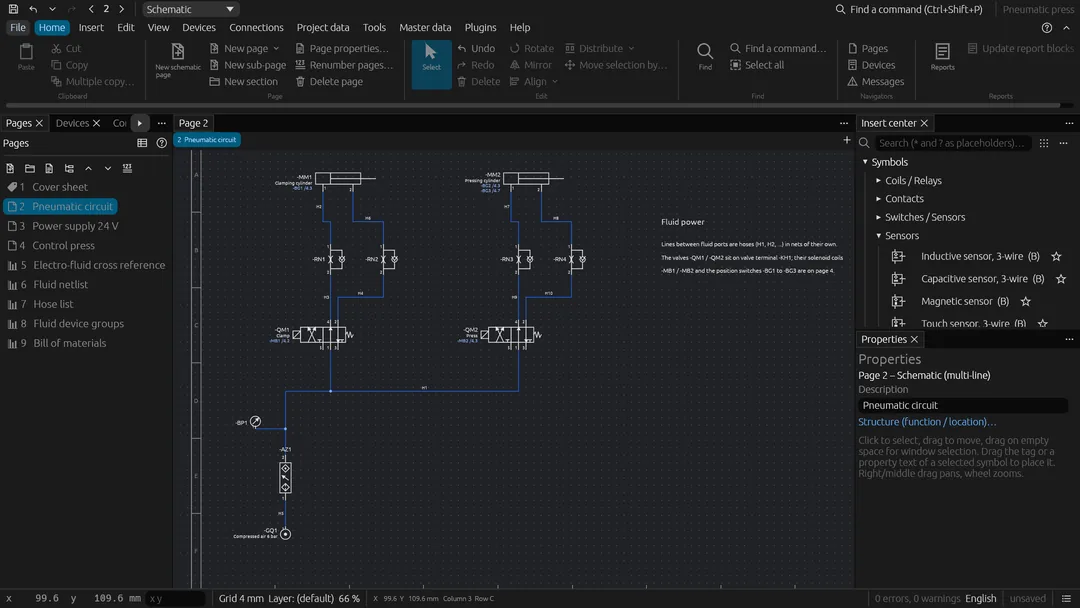
Wires between the ports of fluid power and P&ID symbols are hoses / pipes in their own
nets (not mixed with electrical potentials; a fluid port on an electrical net is an
error), numbered apart from the wires (H1, H2 …), with medium, nominal size, colour
and length, listed in the hose list.
- Fluid netlist: every port gets its function from its ISO 1219 / ISO 5599 designation (supply, pressure P/1, working A/B/2/4, exhaust R/S/3/5, return T, pilot X/Y/Z/12/14, leakage L, in-line) and every hose line its kind (pressure, working, return / exhaust, pilot … line) with its branches (tees).
- Hose configuration: per hose, tube or pipe the line type, part (by the metre), end fittings, maximum pressure and bend radius; the cut length adds the project's cutting allowance per end. Tubes between devices placed on the same mounting plate are routed through its ducts like wires, which gives the length when none is set. The tubing / piping list sums pieces, cut lengths, bends and fittings per type, size and part.
- Fluid device groups: valve terminals, service units, manifolds and power units with their devices in slot order and the number of places.
- Electro-fluid: fluid devices are linked with the electrical devices that actuate
or monitor them (solenoid coils, position and pressure switches); both schematics
show cross references to each other, and Synchronize links solenoid valves with
the coil of the same number (
-QM3→-MB3) and copies function texts. - Checks: pressure lines on a return / exhaust, different media or sizes on one hose or one device, hoses rated below the operating pressure or shorter than their route, solenoid valves without coil, coils without valve, wrong or missing links, full or duplicated groups; open exhausts of pneumatic devices vent to the atmosphere instead of being open connection points.
- Reports: fluid netlist, hose configuration, tubing / piping list, fluid device groups, electro-fluid cross reference.
Process (P&ID)
P&ID symbols (ISO 10628: vessel, pumps, valves, heat exchanger, instruments) support
pre-planning: instruments carry function letters and loop number (TIC 101), the
PCT loops of the pre-planning (Tools › Fluid and process…) list their devices,
and the PCT loop overview shows whether each loop is planned, in engineering or
engineered in the schematic.
Pre-planning
Pre-planning (Devices › Pre-planning…): the plant as a tree of segments
(plant, area, unit, …) with function and location inherited down the tree and the
devices planned in them (tag, kind, description, power, voltage, part, page macro);
the planned power per segment, segment templates, the state of every planned device
against the schematic (planned, engineered, part differs; also a check and the
report Pre-planning), schematic pages generated from the page macros of the
devices not engineered yet, and the exchange as CSV / Excel (commands
preplanning, add_segment, plan_device, …; tools import_preplanning,
generate_preplanning_pages).
Single-line / multi-line engineering
Single-line / multi-line engineering (Devices › Single-line / multi-line…): devices are planned with single-line symbols (breaker, switch-disconnector, motor protection switch, fuse, overload relay, contactor, motor, transformer) on overview pages and engineered in the multi-line schematic; both share the device tag. The window lists each device as planned, engineered, not in the single-line diagram or not matching, and generates the schematic of a single-line page (3-pole power symbols, conductors, contactor coils) or a single-line diagram of the schematic's power devices (arranged from the supply to the loads). The check reports planned devices, mismatching symbols, connections of the single-line diagram missing in the schematic and differing function texts; Synchronize function texts fills empty ones from the other representation.