1 · 最初の回路:押しボタンと表示灯
+24V / 0V の電位、押しボタン、セレクタスイッチ、表示灯、ヒューズを含む1枚の回路図ページ。部品と部品表。
サンプルを見る OpenECraft
サンプルプロジェクト、レベル 5
流体と電気を1つのプロジェクトで:エアサービスユニット、バルブターミナル、5/2 弁、流量制御弁、シリンダを含む空圧回路。ソレノイドコイルと位置スイッチは弁とシリンダに関連付けられています。
プロジェクトをそのまま、OpenECraft の SVG エクスポートで描画しています。
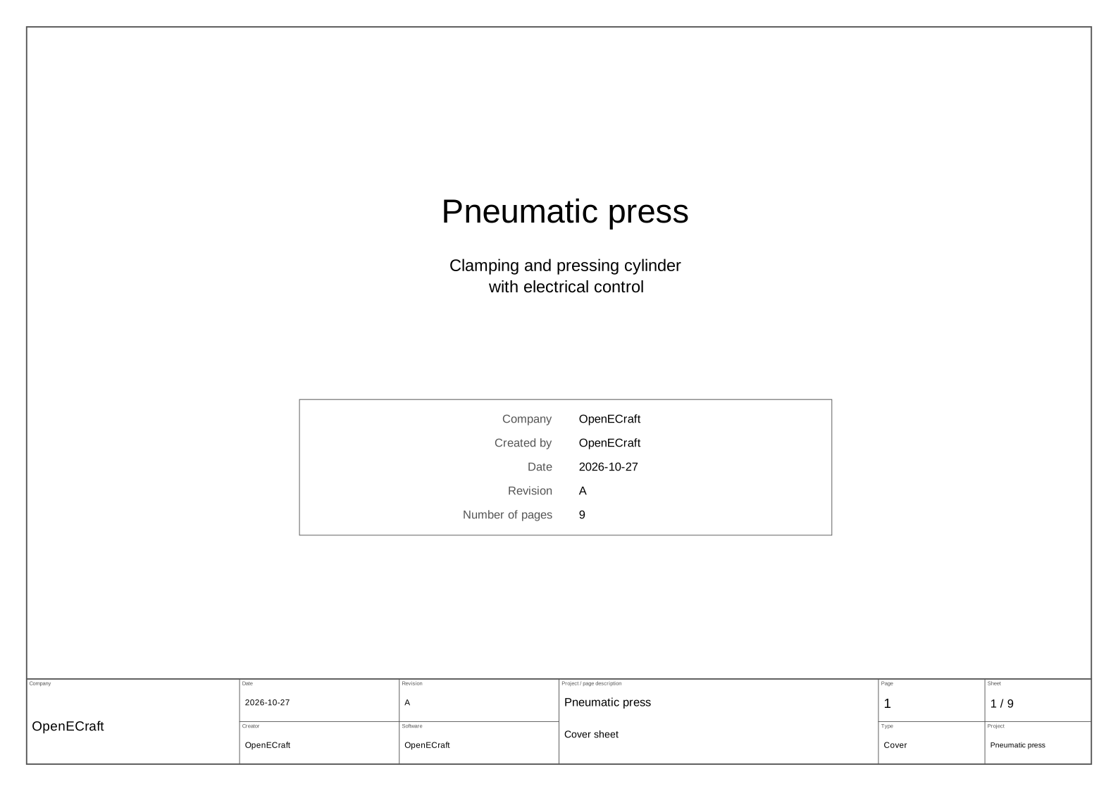
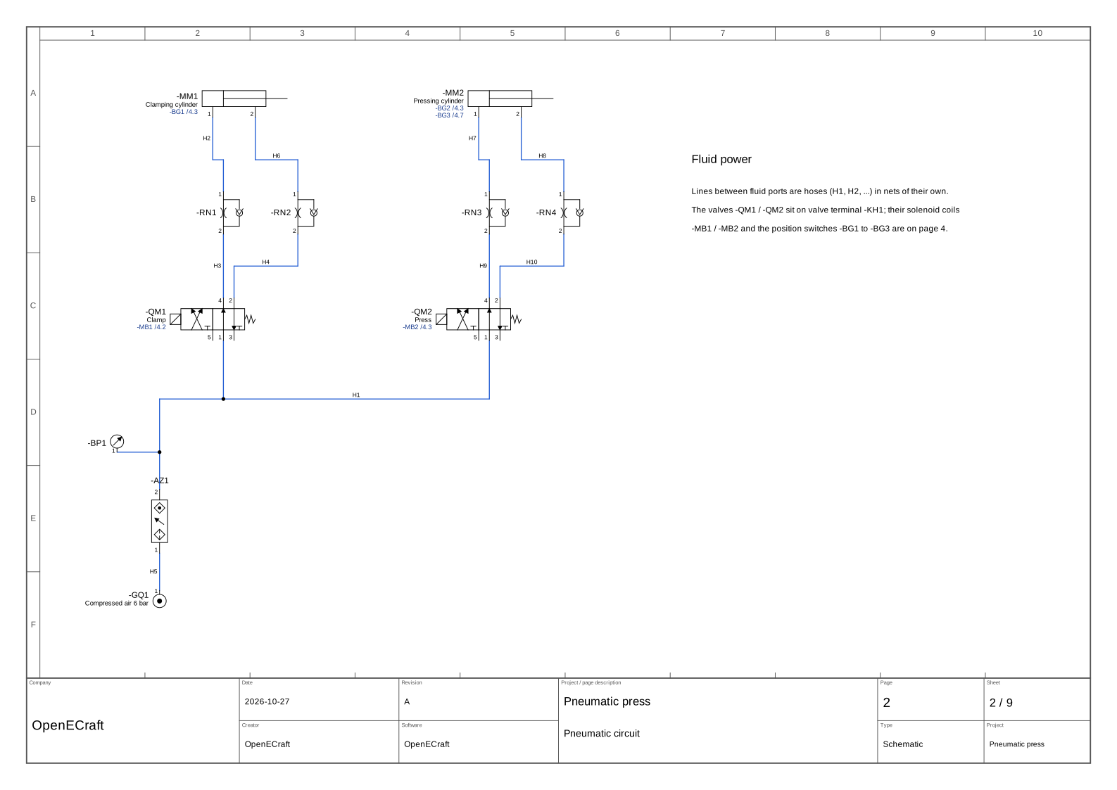
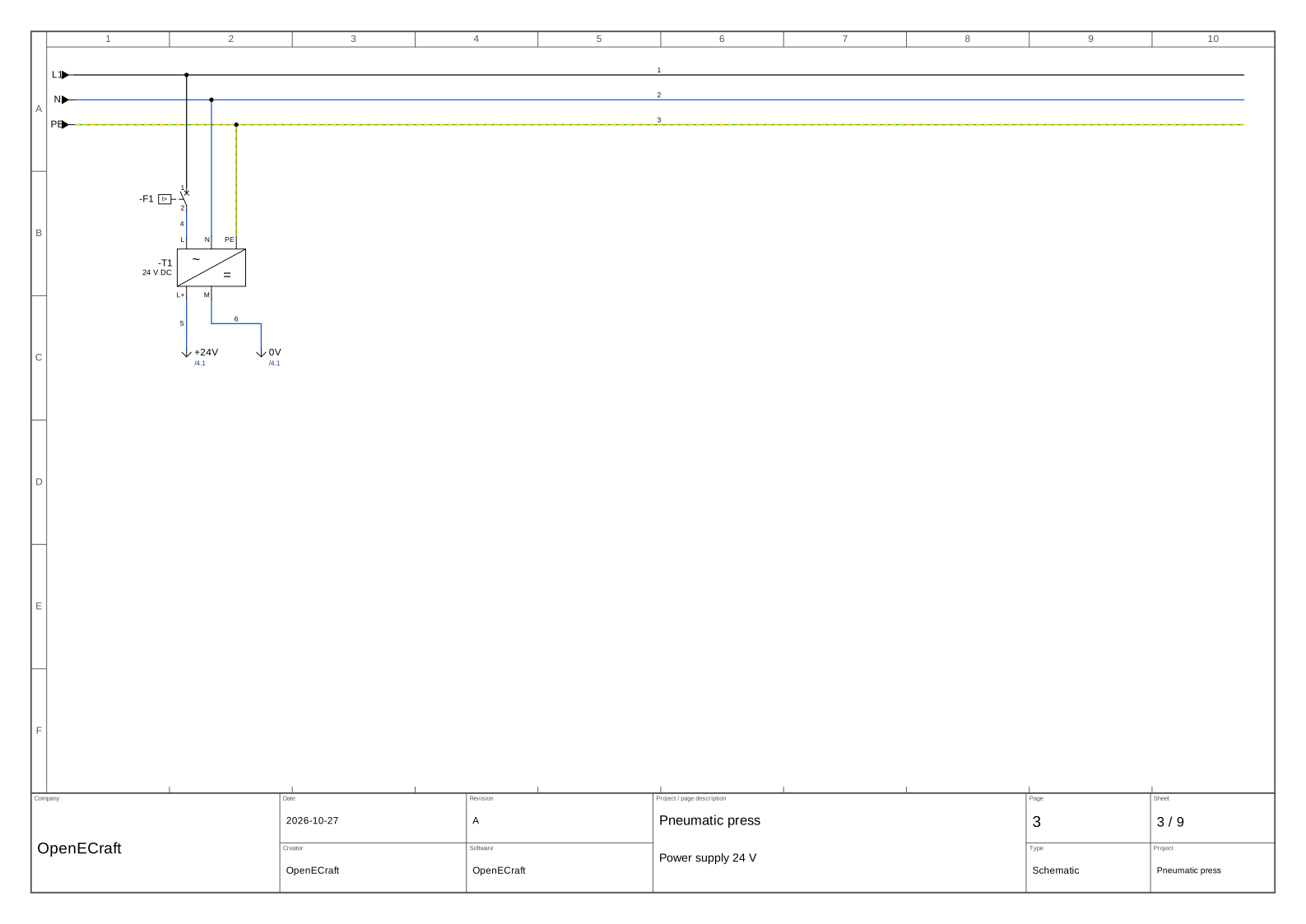
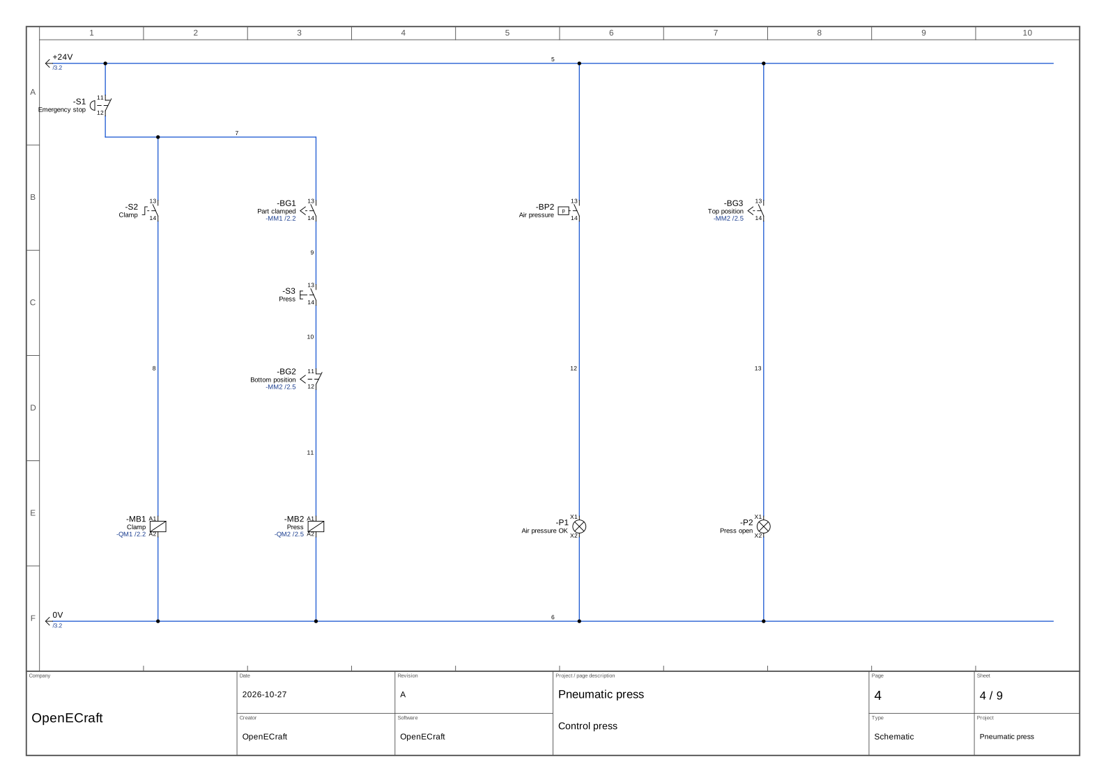
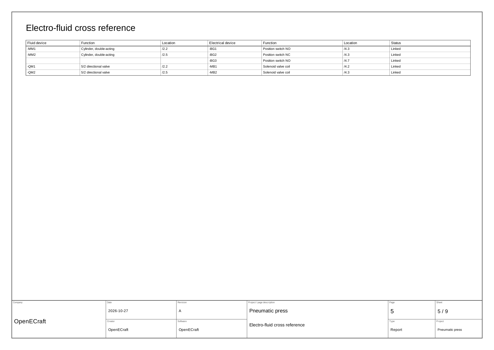
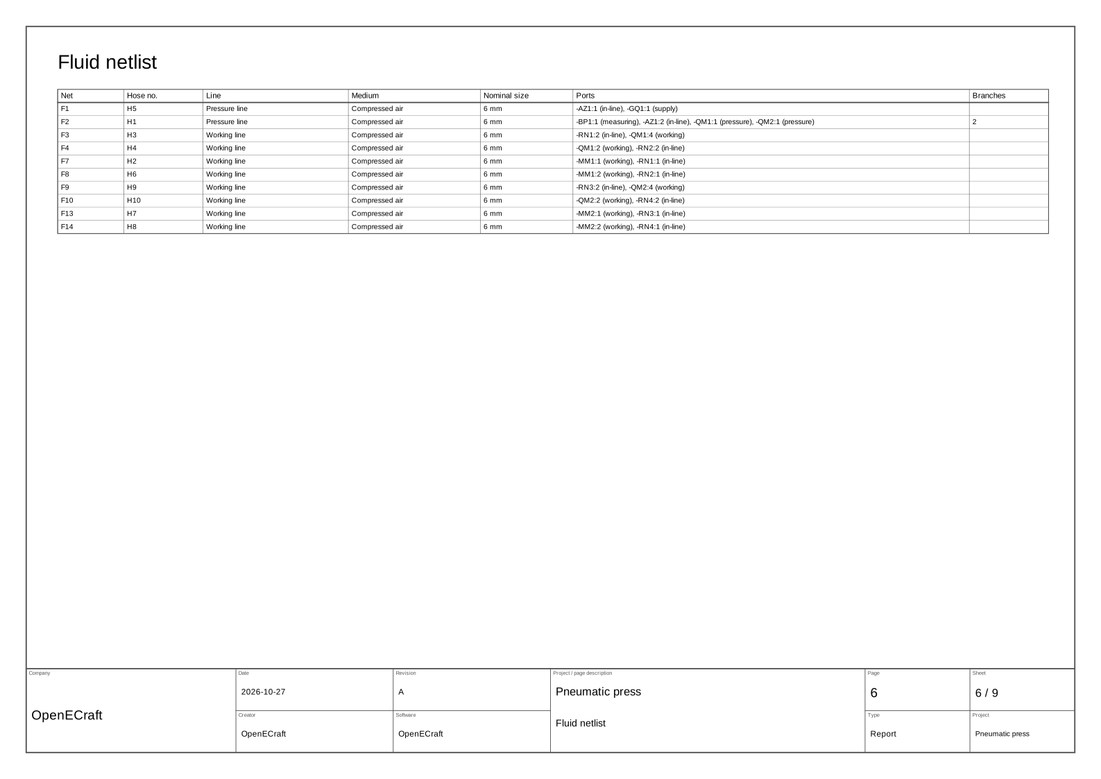
| ページ | 説明 |
|---|---|
| 1 | Cover sheet |
| 2 | Pneumatic circuit |
| 3 | Power supply 24 V |
| 4 | Control press |
| 5 | Electro-fluid cross reference |
| 6 | Fluid netlist |
| 7 | Hose list |
| 8 | Fluid device groups |
| 9 | Bill of materials |
+24V / 0V の電位、押しボタン、セレクタスイッチ、表示灯、ヒューズを含む1枚の回路図ページ。部品と部品表。
サンプルを見るリレーによる起動 / 停止回路:コイルと接点は相互参照と接点イメージを持つ1つの機器を構成します。端子台、線番号、端子図、接続リスト。
サンプルを見る複数ページにわたる主回路と制御回路:主開閉器、モータ保護、インターロック付きの3つの電磁接触器、オンディレイタイマ、中断点、線色付きの電位、モータケーブル、ケーブルレポート。
サンプルを見るデモプロジェクト:PLC の入出力、レール、配線ダクト、扉機器を含む盤の配置図、扉ハーネス、モータケーブル。
サンプルを見るIEC 81346 に基づくプラント構造(機能と場所)、ページセクション、単線結線図、直入れ始動のポンプとインバータ付きのポンプ、デジタルおよびアナログチャンネルを持つ PLC カード、センサプラグ、PLC 割り付け。
サンプルを見る最初のリリース後のコンベヤ:リリース済みでロックされたリビジョン、その後にマークされた変更、赤線入りのレビューコメント、変更要求、承認ワークフロー中のリビジョン B、比較用のベースライン。
サンプルを見る2 台の列盤自立盤に組み込んだポンプ場:ブスバーシステム、レールと配線ダクト、扉機器とハンドル、フィルタファン、照明、PE バー、ケーブルグランド、ケーブル通路、盤内温度計算、ダクト占有率、3D 配線。
サンプルを見る部屋に設置した列盤:L 字形の平面図、内壁、扉とウィンドウ、所定の位置の列盤、壁のコンセント付きレール、壁付けの非常灯、天井下のケーブルラック。
サンプルを見る列盤とポンプのある部屋: 盤の天板のケーブルグランドから給電されるポンプモーター、床置きのポンプとタンク、壁のボールバルブと圧力計、壁の配管ルートに沿って 3D で配線された水回路の DN25 配管。
サンプルを見るA whole building in two rooms: the supply cable and the water main come in through building entries to the house connection box and the remote controlled valve; main distribution with busbars, Hager NH fuse switch disconnectors of three sizes and energy meters; cables and the water pipe pass a wall penetration into the technical room with PLC and pump cabinets, tanks and booster pumps, a compressor with air receiver and dryers and oilers at the outlets, a heat pump with buffer tank and hot water circulation, temperature, pressure and level sensors, a PV system with generator junction box, Victron MultiPlus-II and Inverter RS on the wall, Cerbo GX and Pylontech batteries in a 19-inch rack.
サンプルを見る部品付きのコネクタ: M12 のセンサと M8 のバルブ、GX16 と GX12 の航空コネクタのファンとサーモスタット、D-sub 9 のブザー、2 つの IDC ソケット間のフラットケーブルの操作パネル。プラグウィンドウは各プラグのピン配置を嵌合面に電線と心線の色で示します。
サンプルを見るThe distribution cabinet of an apartment building with an 88 kWp PV system, built from Hager univers parts: busbars with surge arrester and connection point zone, consumption and generation metering with NH1 fuse switch disconnectors on component modules, current transformers, voltage paths and meter cabinets with test terminal blocks, heat pump and inverter feeders, grid and system protection with voltage and frequency relay, buffered 24 V supply, fire brigade switch and a coupling switch with motor operator, undervoltage release and auxiliary switch built in; the cabinet comes with its plinth and lifting eyes.
サンプルを見るTwo bayed Hager univers cabinets: two aluminium supplies on busbar terminals for Al, transformer metering isolated by NH strips with solid links, a power analyser for the zero export of the battery storage, feeders on NH fuse switch disconnector strips of a 185 mm busbar system with current transformers clipped in behind them and energy meters on the Tree bus (DC charging station, sub-distributions, air conditioning), heat pumps behind residual current devices of type B, PV inverters and battery storage behind two coupling switches with motor operators, undervoltage releases and auxiliary switches, cable entry flanges for the large cables.
サンプルを見るThe pump room in a plant of two buildings: the main building with the electrical room on its ground level and the control room above, joined by a shaft; the pump house with pump motor 2, linked by a cable trench between the building entries through which its motor cable is routed; façade lights on the outside walls and a weather station on the roof.
サンプルを見るThe plant of level 15 with an office building: the office on the ground level and the attic under a gable roof whose slopes cut its ceiling down to the knee wall, a stair turned at a quarter landing, roof windows in the front slope; Gira socket outlets, a network outlet and a switch, an MDT KNX push button and room temperature controller, a TV outlet at their mounting heights, a COSMO heating circuit manifold and a single-room control box.
サンプルを見る