1 · First circuit: push buttons and lamps
One schematic page with +24V / 0V potentials, push buttons, a selector switch, lamps and a fuse; parts and the bill of materials.
See the example OpenECraft
Example project, level 5
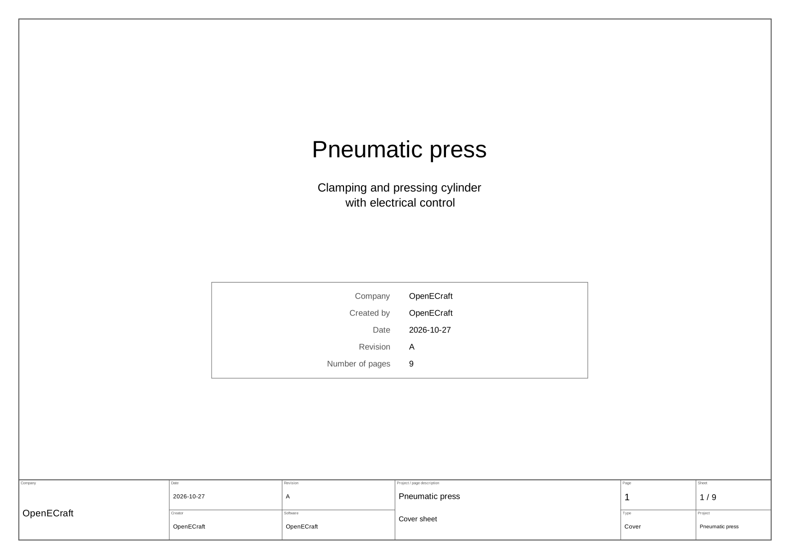
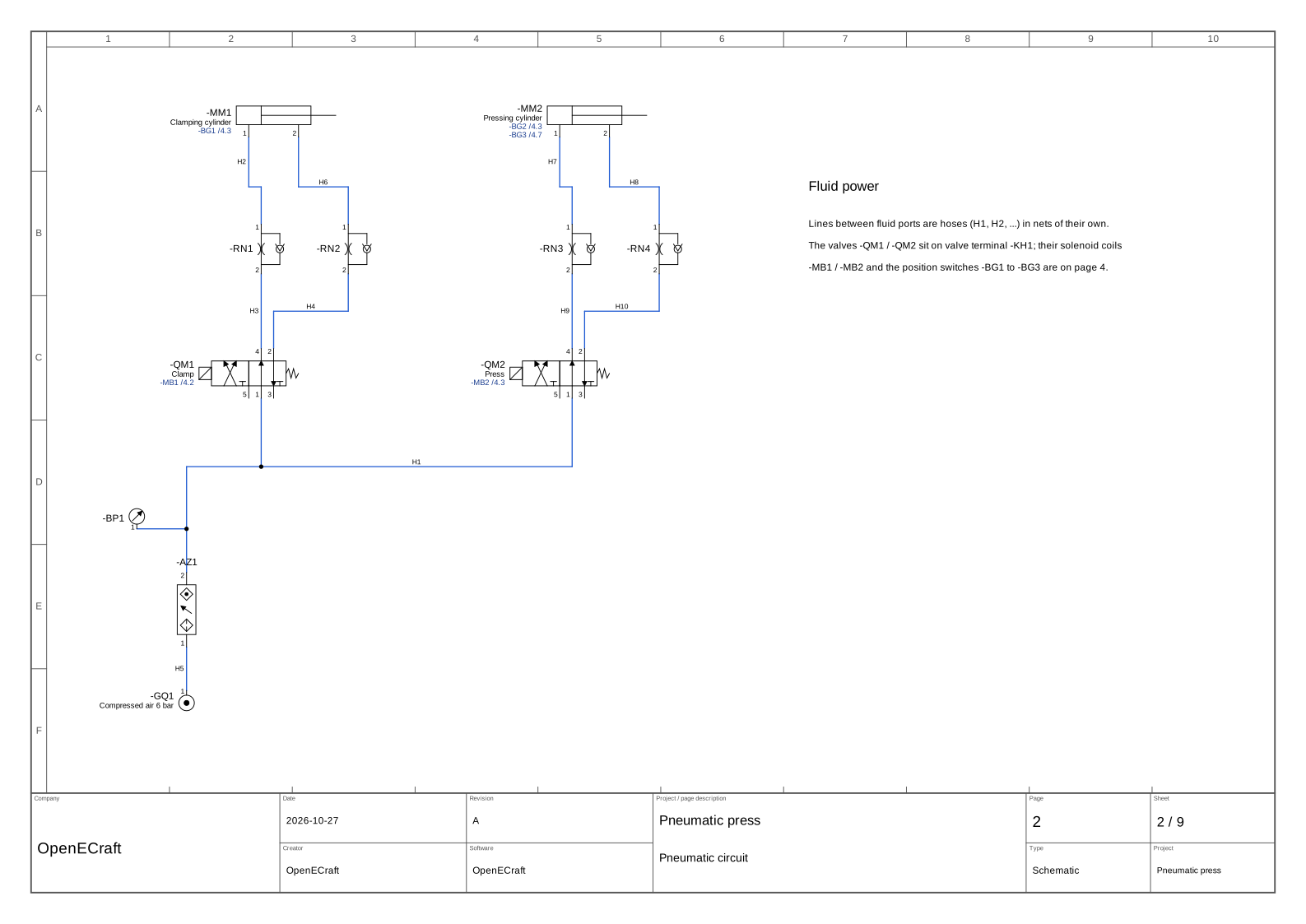
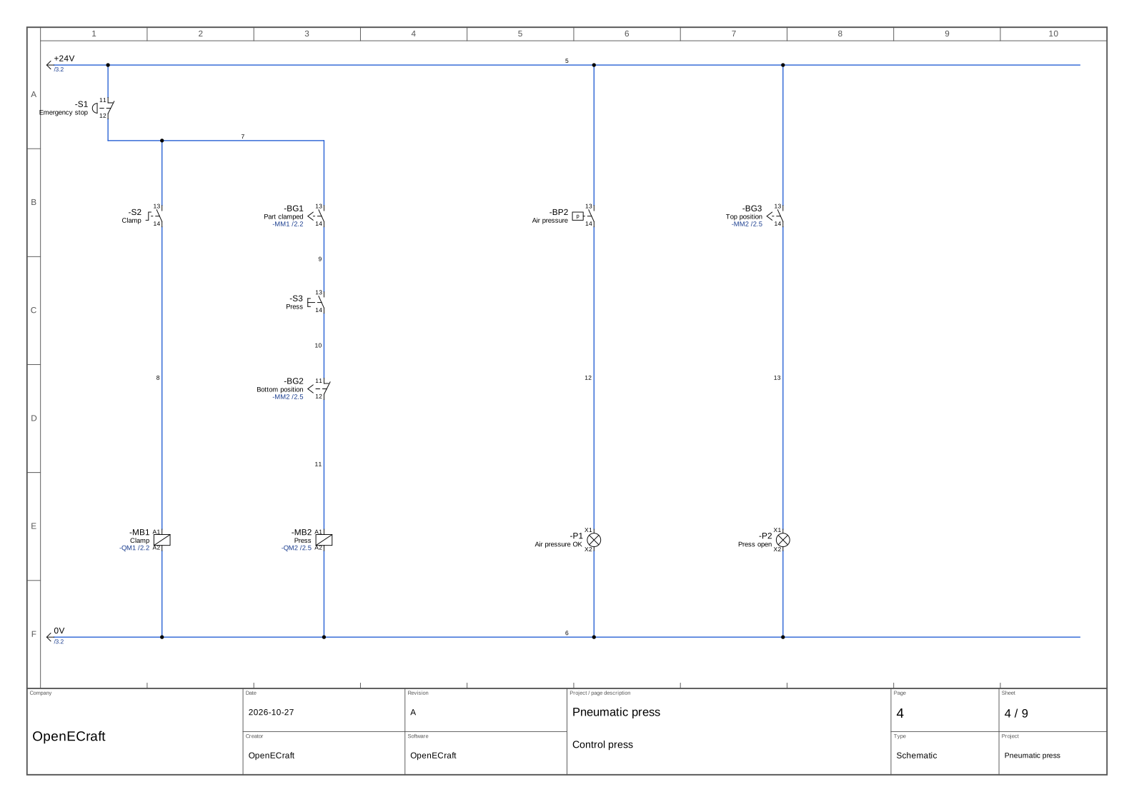
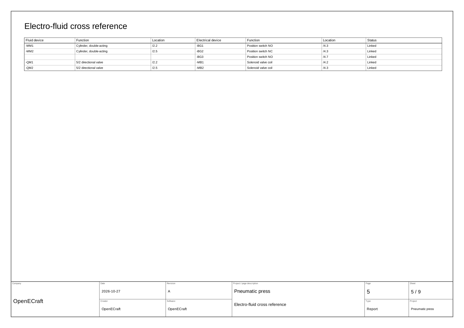
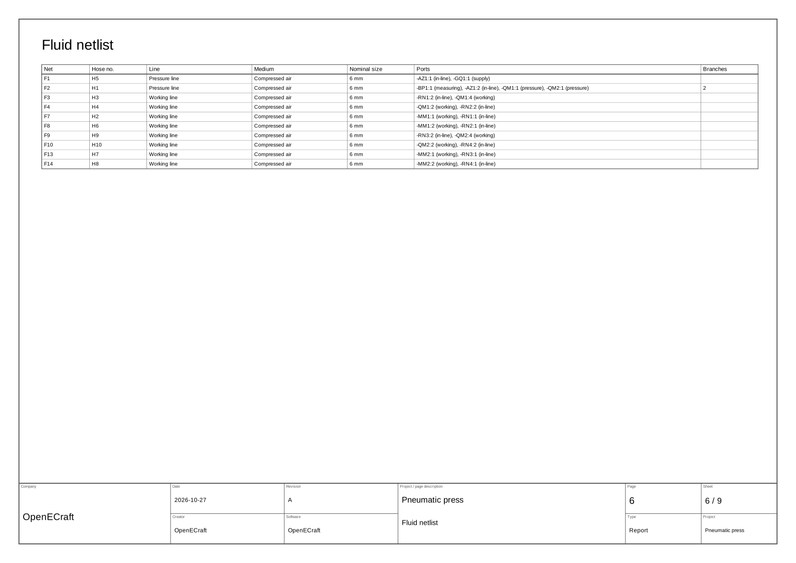
Fluid power and electrics in one project: pneumatic circuit with service unit, valve terminal, 5/2 valves, flow control valves and cylinders; solenoid coils and position switches are linked to the valves and cylinders.
Drawn by the SVG export of OpenECraft, as the project comes.
| Page | Description |
|---|---|
| 1 | Cover sheet |
| 2 | Pneumatic circuit |
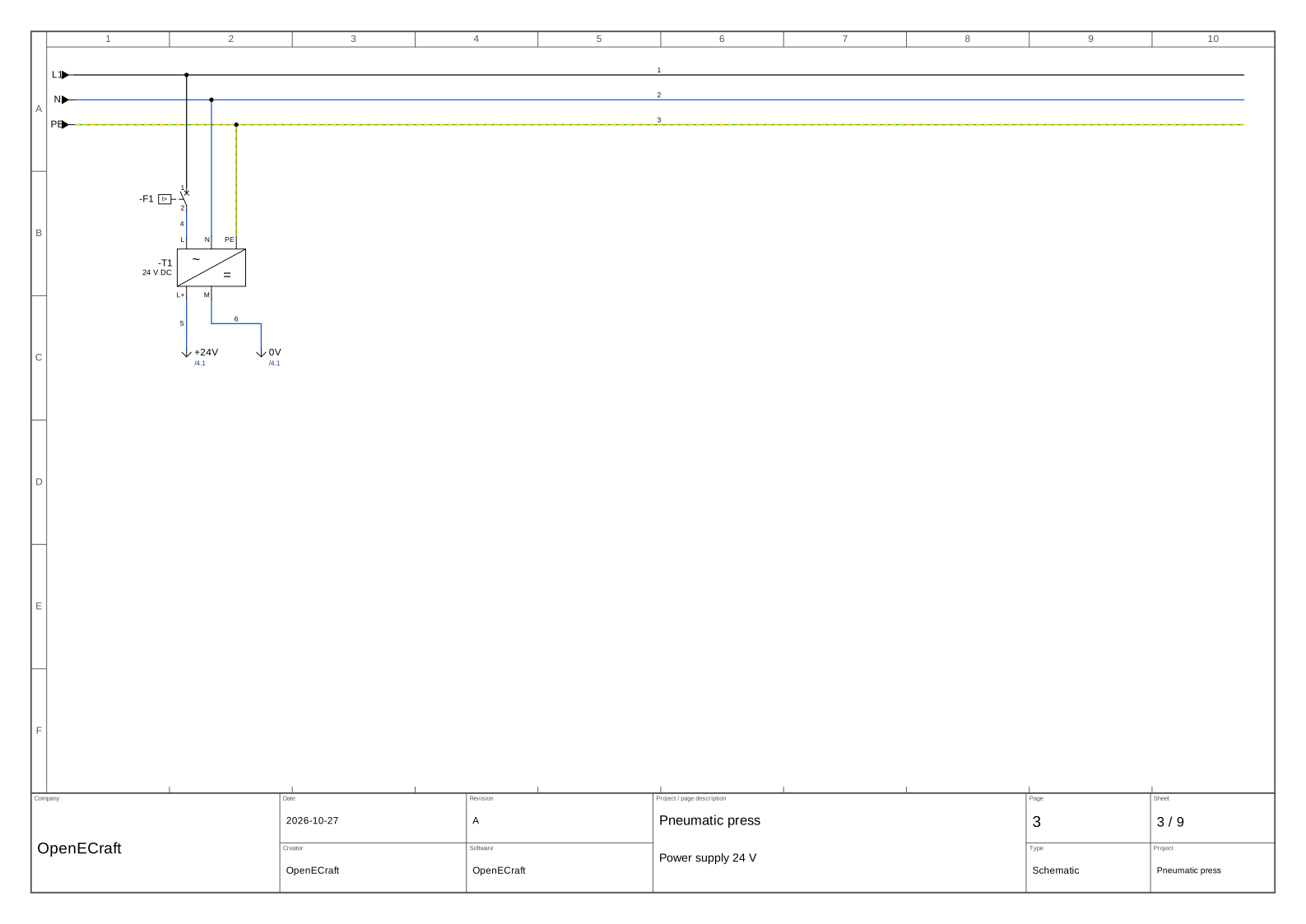
| 3 | Power supply 24 V |
| 4 | Control press |
| 5 | Electro-fluid cross reference |
| 6 | Fluid netlist |
| 7 | Hose list |
| 8 | Fluid device groups |
| 9 | Bill of materials |
One schematic page with +24V / 0V potentials, push buttons, a selector switch, lamps and a fuse; parts and the bill of materials.
See the exampleStart / stop circuit with a relay: coil and contacts form one device with cross references and contact image, terminal strip, wire numbers, terminal diagram and connection list.
See the examplePower and control circuit on several pages: main switch, motor protection, three contactors with interlocks, on-delay timer, interruption points, potentials with wire colours, motor cable and cable reports.
See the exampleThe demo project: PLC inputs and outputs, panel layout of the enclosure with rails, ducts and door devices, door harness and motor cable.
See the examplePlant structure after IEC 81346 (functions and locations), page sections, single-line diagram, a pump direct on line and one with frequency converter, PLC cards with digital and analog channels, a sensor plug and the PLC assignment.
See the exampleThe conveyor after its first release: a released and locked revision, changes marked since, review comments with redlining, a change request, revision B in the approval workflow and a baseline to compare with.
See the exampleThe pump station built into two bayed floor-standing enclosures: busbar system, rails and ducts, door devices and handles, filter fan, light, PE bar, cable glands, a cable passage, climate calculation, duct fill and 3D routing.
See the exampleThe cabinet line-up in its room: L-shaped floor plan, inner wall, door and window, the line-up at its place, a mounting rail with a socket outlet on a wall, a wall-mounted emergency light and a cable tray under the ceiling.
See the exampleThe room of the line-up with its pumps: pump motors fed through cable glands in the roofs of the cabinets, a pump and a vessel standing on the floor, ball valves and a gauge on the wall, and the DN25 pipes of the water circuit routed in 3D along a pipe run on the wall.
See the exampleA whole building in two rooms: the supply cable and the water main come in through building entries to the house connection box and the remote controlled valve; main distribution with busbars, Hager NH fuse switch disconnectors of three sizes and energy meters; cables and the water pipe pass a wall penetration into the technical room with PLC and pump cabinets, tanks and booster pumps, a compressor with air receiver and dryers and oilers at the outlets, a heat pump with buffer tank and hot water circulation, temperature, pressure and level sensors, a PV system with generator junction box, Victron MultiPlus-II and Inverter RS on the wall, Cerbo GX and Pylontech batteries in a 19-inch rack.
See the examplePlug connectors with their parts: a sensor on M12 and a valve on M8, a fan and its thermostat on GX16 and GX12 aviation connectors, a buzzer on a D-sub 9 and an operator panel on a ribbon cable between two IDC sockets; the plugs window shows the pin-out of each plug on its mating faces with the wire and core colours.
See the exampleThe distribution cabinet of an apartment building with an 88 kWp PV system, built from Hager univers parts: busbars with surge arrester and connection point zone, consumption and generation metering with NH1 fuse switch disconnectors on component modules, current transformers, voltage paths and meter cabinets with test terminal blocks, heat pump and inverter feeders, grid and system protection with voltage and frequency relay, buffered 24 V supply, fire brigade switch and a coupling switch with motor operator, undervoltage release and auxiliary switch built in; the cabinet comes with its plinth and lifting eyes.
See the exampleTwo bayed Hager univers cabinets: two aluminium supplies on busbar terminals for Al, transformer metering isolated by NH strips with solid links, a power analyser for the zero export of the battery storage, feeders on NH fuse switch disconnector strips of a 185 mm busbar system with current transformers clipped in behind them and energy meters on the Tree bus (DC charging station, sub-distributions, air conditioning), heat pumps behind residual current devices of type B, PV inverters and battery storage behind two coupling switches with motor operators, undervoltage releases and auxiliary switches, cable entry flanges for the large cables.
See the exampleThe pump room in a plant of two buildings: the main building with the electrical room on its ground level and the control room above, joined by a shaft; the pump house with pump motor 2, linked by a cable trench between the building entries through which its motor cable is routed; façade lights on the outside walls and a weather station on the roof.
See the exampleThe plant of level 15 with an office building: the office on the ground level and the attic under a gable roof whose slopes cut its ceiling down to the knee wall, a stair turned at a quarter landing, roof windows in the front slope; Gira socket outlets, a network outlet and a switch, an MDT KNX push button and room temperature controller, a TV outlet at their mounting heights, a COSMO heating circuit manifold and a single-room control box.
See the example