1 · Pierwszy obwód: przyciski i lampki
Jedna strona schematu z potencjałami +24V / 0V, przyciskami, przełącznikiem wyboru, lampkami i bezpiecznikiem; artykuły i zestawienie materiałów.
Zobacz przykład OpenECraft
Projekt przykładowy, poziom 11
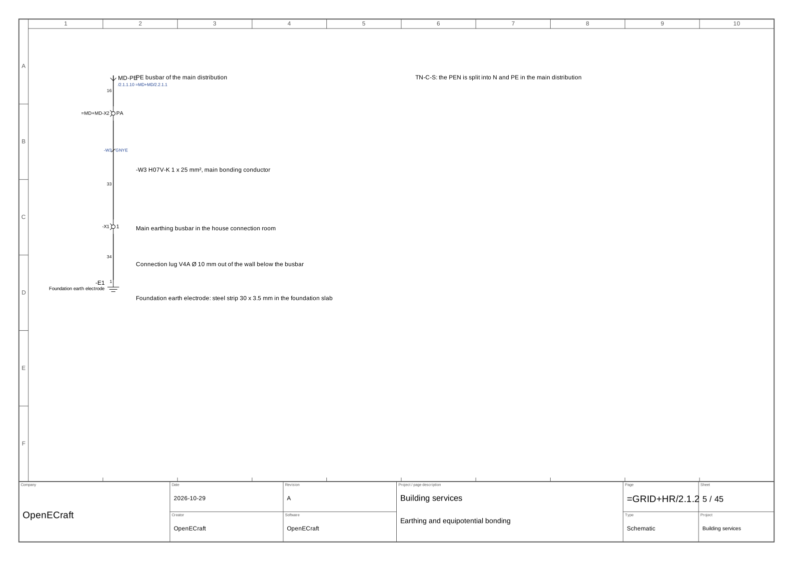
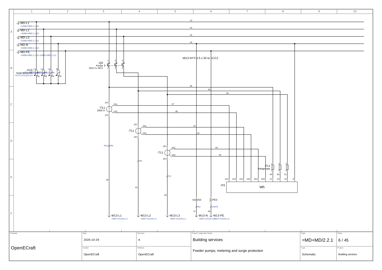
A whole building in two rooms: the supply cable and the water main come in through building entries to the house connection box and the remote controlled valve; main distribution with busbars, Hager NH fuse switch disconnectors of three sizes and energy meters; cables and the water pipe pass a wall penetration into the technical room with PLC and pump cabinets, tanks and booster pumps, a compressor with air receiver and dryers and oilers at the outlets, a heat pump with buffer tank and hot water circulation, temperature, pressure and level sensors, a PV system with generator junction box, Victron MultiPlus-II and Inverter RS on the wall, Cerbo GX and Pylontech batteries in a 19-inch rack.
Narysowane przez eksport SVG programu OpenECraft, tak jak projekt jest dostarczany.
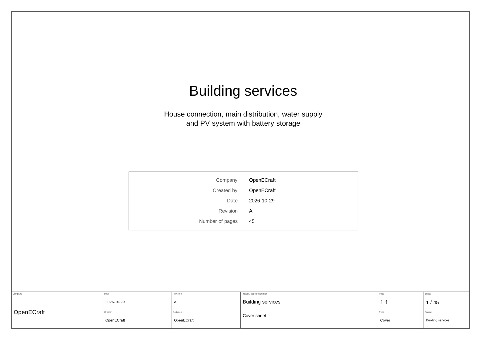
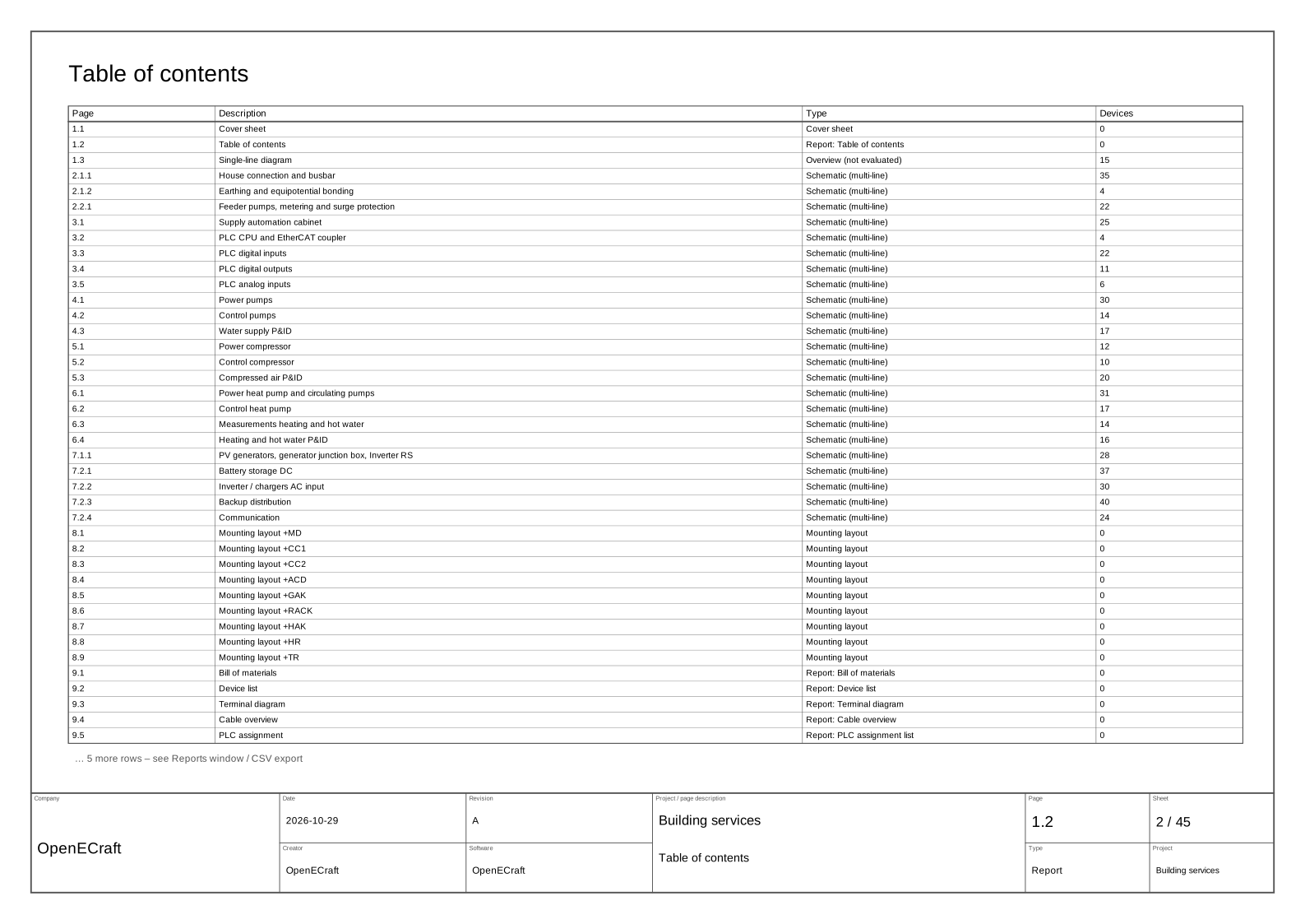
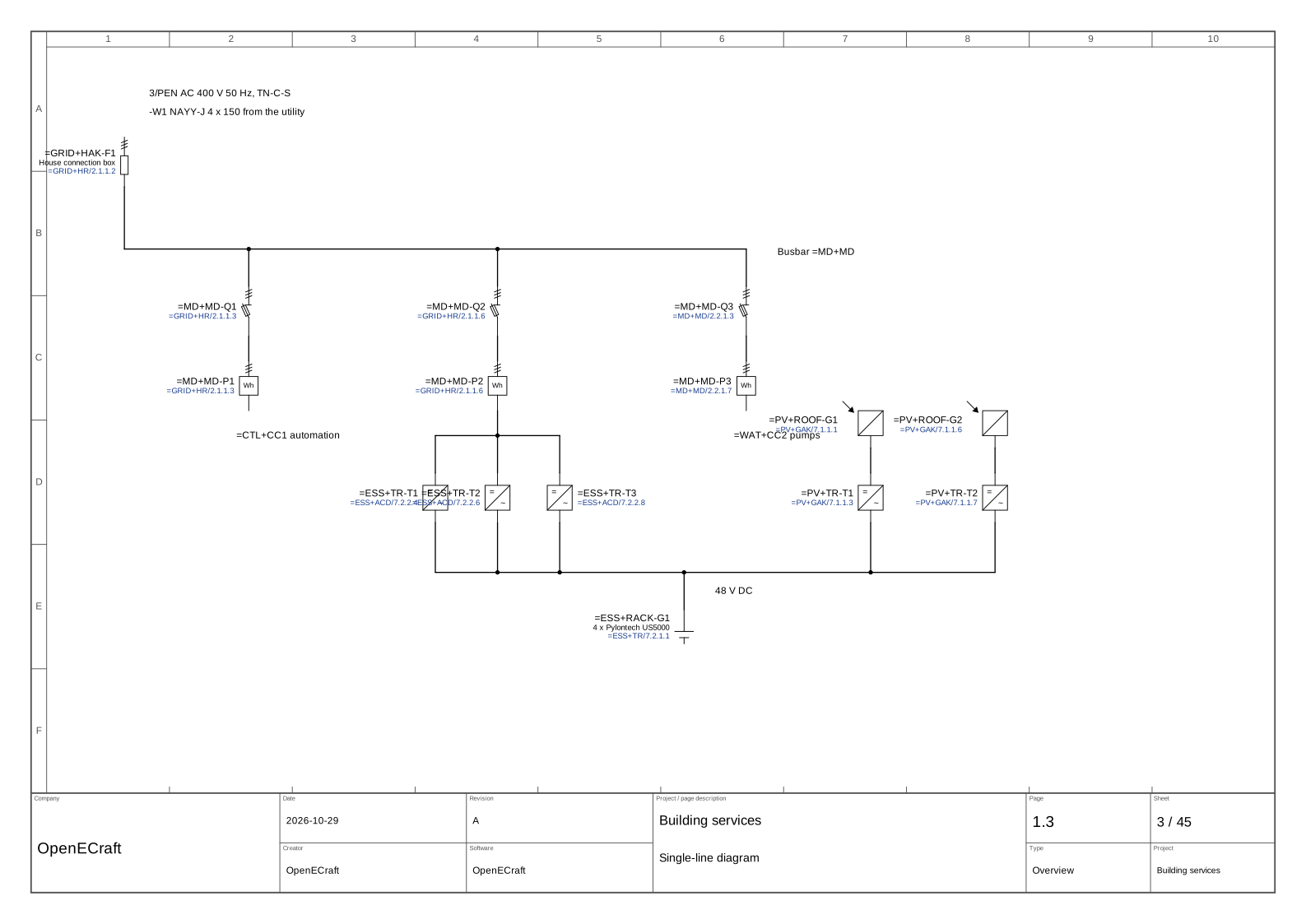
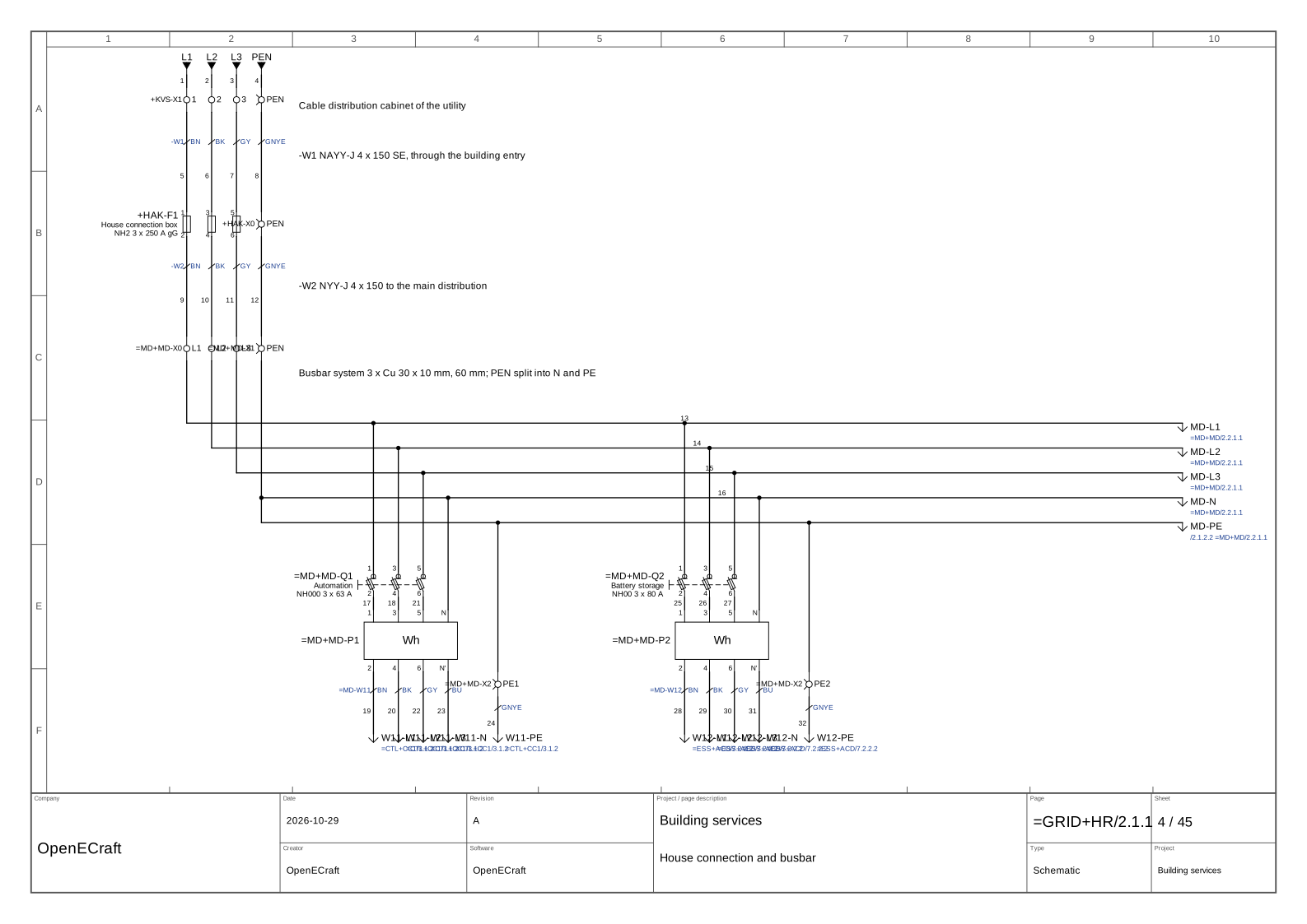
| Strona | Opis |
|---|---|
| 1.1 | Cover sheet |
| 1.2 | Table of contents |
| 1.3 | Single-line diagram |
| 2.1.1 | House connection and busbar |
| 2.1.2 | Earthing and equipotential bonding |
| 2.2.1 | Feeder pumps, metering and surge protection |
| 3.1 | Supply automation cabinet |
| 3.2 | PLC CPU and EtherCAT coupler |
| 3.3 | PLC digital inputs |
| 3.4 | PLC digital outputs |
| 3.5 | PLC analog inputs |
| 4.1 | Power pumps |
| 4.2 | Control pumps |
| 4.3 | Water supply P&ID |
| 5.1 | Power compressor |
| 5.2 | Control compressor |
| 5.3 | Compressed air P&ID |
| 6.1 | Power heat pump and circulating pumps |
| 6.2 | Control heat pump |
| 6.3 | Measurements heating and hot water |
| 6.4 | Heating and hot water P&ID |
| 7.1.1 | PV generators, generator junction box, Inverter RS |
| 7.2.1 | Battery storage DC |
| 7.2.2 | Inverter / chargers AC input |
| 7.2.3 | Backup distribution |
| 7.2.4 | Communication |
| 8.1 | Mounting layout +MD |
| 8.2 | Mounting layout +CC1 |
| 8.3 | Mounting layout +CC2 |
| 8.4 | Mounting layout +ACD |
| 8.5 | Mounting layout +GAK |
| 8.6 | Mounting layout +RACK |
| 8.7 | Mounting layout +HAK |
| 8.8 | Mounting layout +HR |
| 8.9 | Mounting layout +TR |
| 9.1 | Bill of materials |
| 9.2 | Device list |
| 9.3 | Terminal diagram |
| 9.4 | Cable overview |
| 9.5 | PLC assignment |
| 9.6 | Plug diagram |
| 9.7 | Panel legend |
| 9.8 | 3D routing |
| 9.9 | Hose list |
| 9.10 | 19-inch rack elevation |
Jedna strona schematu z potencjałami +24V / 0V, przyciskami, przełącznikiem wyboru, lampkami i bezpiecznikiem; artykuły i zestawienie materiałów.
Zobacz przykładObwód start / stop z przekaźnikiem: cewka i styki tworzą jedno urządzenie z odsyłaczami i obrazem styków, listwa zaciskowa, numery przewodów, schemat listwy i lista połączeń.
Zobacz przykładObwód główny i sterowania na kilku stronach: wyłącznik główny, zabezpieczenie silnika, trzy styczniki z blokadami, przekaźnik czasowy opóźnionego załączania, punkty przerwania, potencjały z kolorami przewodów, kabel silnika i zestawienia kabli.
Zobacz przykładProjekt demonstracyjny: wejścia i wyjścia PLC, rozmieszczenie w obudowie z szynami, korytkami i urządzeniami na drzwiach, wiązka drzwiowa i kabel silnika.
Zobacz przykładTechnika płynowa i elektryka w jednym projekcie: schemat pneumatyczny z zespołem przygotowania powietrza, wyspą zaworową, zaworami 5/2, zaworami dławiąco-zwrotnymi i siłownikami; cewki elektrozaworów i wyłączniki krańcowe są powiązane z zaworami i siłownikami.
Zobacz przykładStruktura instalacji według IEC 81346 (funkcje i lokalizacje), sekcje stron, schemat jednokreskowy, pompa z rozruchem bezpośrednim i pompa z przemiennikiem częstotliwości, karty PLC z kanałami cyfrowymi i analogowymi, wtyk czujnika i przydział PLC.
Zobacz przykładPrzenośnik po pierwszym wydaniu: wydana i zablokowana rewizja, zmiany oznaczone od tego czasu, komentarze z przeglądu z oznaczeniami na czerwono, wniosek o zmianę, rewizja B w procesie zatwierdzania i stan bazowy do porównania.
Zobacz przykładPrzepompownia zabudowana w dwóch szeregowanych szafach stojących: system szyn zbiorczych, szyny i korytka, urządzenia na drzwiach i uchwyty, wentylator z filtrem, oświetlenie, szyna PE, dławnice kablowe, przepust kablowy, obliczenia klimatyzacji, zapełnienie korytek i trasowanie 3D.
Zobacz przykładSzereg szaf w swoim pomieszczeniu: rzut w kształcie litery L, ściana wewnętrzna, drzwi i okno, szereg szaf na swoim miejscu, szyna z gniazdem na ścianie, oprawa awaryjna montowana na ścianie i korytko kablowe pod sufitem.
Zobacz przykładPomieszczenie szeregu szaf z pompami: silniki pomp zasilane przez dławiki kablowe w dachach szaf, pompa i zbiornik stojące na podłodze, zawory kulowe i manometr na ścianie oraz rury DN25 obiegu wody prowadzone w 3D wzdłuż trasy rurociągu na ścianie.
Zobacz przykładZłącza z ich częściami: czujnik na M12 i zawór na M8, wentylator i jego termostat na złączach lotniczych GX16 i GX12, brzęczyk na D-sub 9 oraz panel operatora na taśmie między dwoma złączami IDC; okno złączy pokazuje rozkład pinów każdego złącza na jego stronach styku z kolorami przewodów i żył.
Zobacz przykładThe distribution cabinet of an apartment building with an 88 kWp PV system, built from Hager univers parts: busbars with surge arrester and connection point zone, consumption and generation metering with NH1 fuse switch disconnectors on component modules, current transformers, voltage paths and meter cabinets with test terminal blocks, heat pump and inverter feeders, grid and system protection with voltage and frequency relay, buffered 24 V supply, fire brigade switch and a coupling switch with motor operator, undervoltage release and auxiliary switch built in; the cabinet comes with its plinth and lifting eyes.
Zobacz przykładTwo bayed Hager univers cabinets: two aluminium supplies on busbar terminals for Al, transformer metering isolated by NH strips with solid links, a power analyser for the zero export of the battery storage, feeders on NH fuse switch disconnector strips of a 185 mm busbar system with current transformers clipped in behind them and energy meters on the Tree bus (DC charging station, sub-distributions, air conditioning), heat pumps behind residual current devices of type B, PV inverters and battery storage behind two coupling switches with motor operators, undervoltage releases and auxiliary switches, cable entry flanges for the large cables.
Zobacz przykładThe pump room in a plant of two buildings: the main building with the electrical room on its ground level and the control room above, joined by a shaft; the pump house with pump motor 2, linked by a cable trench between the building entries through which its motor cable is routed; façade lights on the outside walls and a weather station on the roof.
Zobacz przykładThe plant of level 15 with an office building: the office on the ground level and the attic under a gable roof whose slopes cut its ceiling down to the knee wall, a stair turned at a quarter landing, roof windows in the front slope; Gira socket outlets, a network outlet and a switch, an MDT KNX push button and room temperature controller, a TV outlet at their mounting heights, a COSMO heating circuit manifold and a single-room control box.
Zobacz przykład